what. if. you. like. it?
Well fuck me then lol. I sure hope something like that doesn’t work
4 Likes
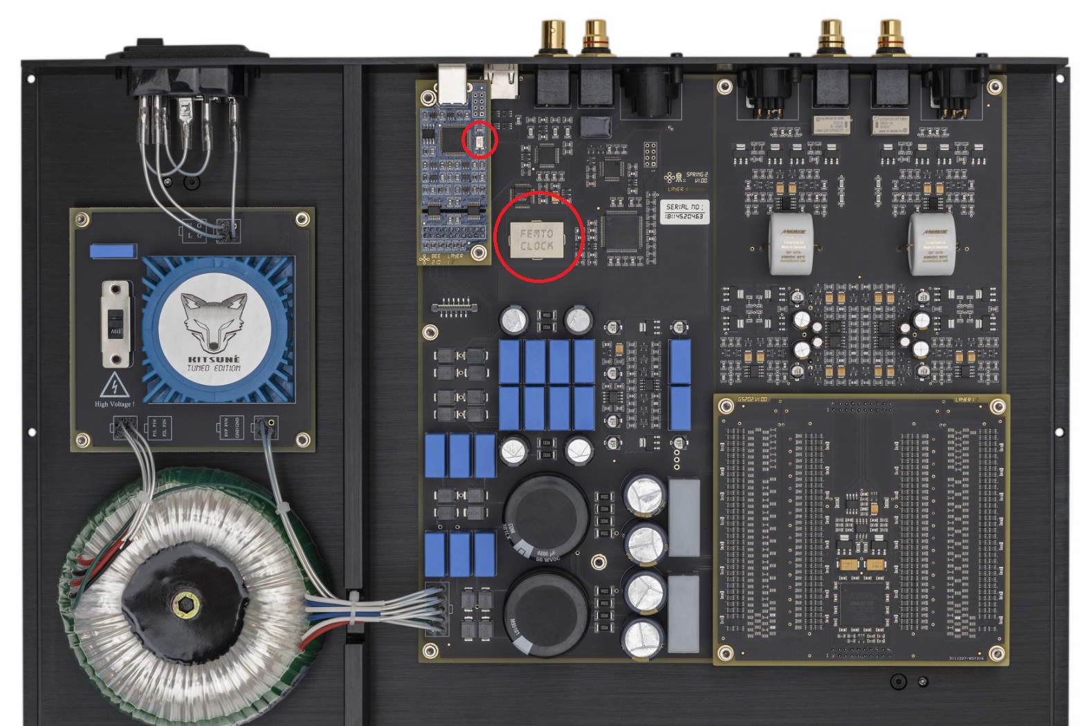
Okay, forgive me for being thick since I’m not entirely understanding how the hand off from USB to the DAC is made and what exactly happens in between. I know the big words and theory but in the above pretty popular USB board they both have clocks, and in the Spring 2 board here you also see the clock on the USB board and close by the Femto Clock on the DAC. So the quality of those clocks has to matter. Is the question then, what is the better sum, DDC and internal DAC clock or USB (clocks) and internal DAC clock?
So if the signal is coming from USB or the signal is coming from another input, say AES, they’re still both being potentially corrected by the on board clock in the DAC. So based on what I’m hearing you guys say is that in some cases the signal coming in from a re-clocker may be as good or better than the clock in the DAC. In other cases the clock in the DAC may be better than the signal coming in from the DDC clock, so it may not make a difference if that’s the case. In some cases, especially if whatever is happening in the USB onboard card is good and then is sent to the DAC clock which is better than said DDC re-clocker. In both cases the DAC clock is a higher caliber, so subsequently, it’s pointless to use the DDC.
I’m trying to answer my own question here, and maybe that way proving to myself I grasp the concept.
Think of it as a small computer.
Schiit actually uses a PIC uController, but USB data basically comes in packets on a “clock” (not the DAC clock), the uController buffers some number of packets (at least one probably more).
And takes values out of that buffer and on some clock either it’s own, or provided additionally and shoves them through a Driver IC, or pumps them directly onto an I2S channel.
It’s a bit more complex than that, the packets do contain a checksum, that the DAC can check, but it has no way to requests a resend if the packet is bad.
Now there are purpose built IC’s for this and Some companies use an FPGA to handle this, but you have to have all of the trappings of a USB receiver and you have to buffer the data, and output it on a clock you generate.
In your image the small clock chip is probably for the USB interface controller.
Data from AES/SPDIF looks superficially similar, but the difference is the data is synchronously clocked, so it’s much simpler to extract, it’s just a sequence of bits on a wire at an exact multiple of the output clock, with metadata embedded.
There is no need to Buffer or generate a clock for it.
I2S is like AES/SPDIF except that the clock isn’t in the data, it’s sent on a separate wire, and it’s what the input the actual DAC chip would likely take on a circuit board.
3 Likes
Puhh hmmm,
It all sounds good, but it doesn’t justify the price in my opinion to get the last 10% out if you want to.
I went a different way.
Matirx Audio Element H with separate power supply,
Singxer Su 2 via I2S to the Dac.
The Element H alone got a lot out of it maybe even more than the Su 2.
The ysu 2 tended to make everything seem warmer and more 3 dimensional I would say.
All in all, I was close to the $1,000 mark when you add it all up, which is also quite a lot.
You are right about the usb port on the pc.
Due to the construction, everything goes through the mainboard plus the power peaks of the power supply.
You can counteract this very well by taking a simple usb pcie card and creating a direct connection.
It does not necessarily have to be the Element H.
However, even though it is connected to the board and supplied with external power, it has the advantage of having its own circuit instead of that of the PC’s power supply.
Nevertheless, if you take a PCie USB card and have a good power supply on the PC, it also brings another benefit.
Also you are right about Usb, the reason will be simply the cost because it is cheap.
Technically, more would certainly be possible, probably also with I2S, if it were simply developed better.
Just the data you could send with a hdmi port would be an advantage in my opinion than with usb.
And you probably wouldn’t need such extreme power supplies that cost vast sums of money. as long as they are cleanly constructed, everything would certainly be good and sufficient there too.
The Raspberry is certainly quite good and rightly popular.
But the catch is supposed to be the power supply because the power supply is not that good and a good one costs as much as the Pi2, which makes it unattractive again.
Because for that money you can really get a Su2 or Spif2 and connect it directly without any frills.
And the performance is relatively good.
These last couple of comments helped a lot. Thanks.
All in a days work for the life of a PLL designer. I spent the first 5 years of my career as a IC design engineer working on phase-locked loops. Mostly designing precision clock generation PLLs, with some work on clock/data recovery PLLs. So I won’t comment on USB data Tx/Rx topic, I don’t have much experience there. But regarding SPDIF, the comments / observations made in this thread are generally correct:
yes
yes
yes, but still with some analog limitations.
So here’s more of the story:
From a system stand point a PLL is just a low pass filter block. But instead of being in the frequency domain (as we are used to thinking about for audio filters), it is in the phase domain. Phase is just another way of describing a time shift of a signal. So a PLL filters time shifts above a certain cutoff “phase”. (Think 3dB down point, similar to any other filter.)
In general, to produce a low “phase noise” clock (ie low jitter) from a PLL you want low bandwidth. (There’s many caveats to this statement, but stick with me for now.) The output of the PLL will track the phase variation of a periodic input that is “in band”, and reject phase variation “out of band”. Large clock jitter is rejected, small clock jitter passes through.
BUT in clock recovery circuits (such as those in SPDIF clock recovery circutis) you need the bandwidth to be wide enough to track changes in the incoming data stream. You can’t have the bandwidth so tight that you start mis-clocking data if there’s a slight variation in the input data rate. This is contrary to what you want to have for a very low jitter output. So, as in most design challenges, it’s a balancing act.
An interesting example of this issue is the iFi SPDIF iPurifier products. If you feed them too noisy of a data stream they struggle to lock to the correct clock frequency. This product seems to be over optimized for low noise. I found this out by driving it with the optical output of a Chromecast audio. It is known to have a noisy optical output, and at the 88.2kHz sampling rate it is worse than 96kHz. So whenver a track played at 88.2kHz via the CCA it would loose lock, and the output would be garbage. This was a pain, until I diteched the CCA. But it was good to see that the “low noise” SPDIF reclocker was actually low bandwidth - theoretically beneficial.
If you cascade multiple PLL blocks in series you theoretically get additional filtering benefits. The first PLL filters the phase noise, then the second PLL filters again, etc. The reality of the jitter benefit at the output depends on the bandwidth of each PLL block. If you put a wider band PLL after a narrow band PLL you won’t get much benefit. But if the cascaded PLL is lower bandwidth (or similar bandwidth) it will have some benefit. And for a more advanced clocking system (not sure if anyone does this, but it’s possible) you can cascade two PLL’s where the the loop bandwidth for each PLL is optimized for a specific job: first one is clock recovery, second one is low phase noise.
That said, the output of a PLL is an analog circuit - a voltage controlled oscillator (VCO). And noise from the VCO is significant. In fact, the PLL high-pass filters noise from the VCO - that is any noise that is contributed to the output clock that originates in the VCO (or VCO power supply) that is high phase offset from the carrier will show up directly at the output. The PLL does nothing to improve this. Noise from the VCO is almost open loop from this perspective.
This is why typically a PLL will have separate internal LDO voltage regulators for the digital input side and the analog output side. This minimizes supply noise injection into the VCO. If a given reclocker has a noisier VCO output, it may not give a benefit when cascaded after the first reclocker. It also can impact why better external powers supplies can have mixed results on performance - a shitty internal regulator may negate the benefit of the nice external regulator.
PLL’s can do a very nice job recovering clocks reliably that don’t misclock the data (ie low bit error rate). But it is much harder to recover a clock and maintain that clock with low noise. Doing that takes much more careful design, hence the benefit we hear when using better reclockers, better power supplies, and cascading reclockers. But if the last item in the signal chain (ie the DAC) has an internally poor PLL implementation, it may not matter at all how clean the input signal is.
wow… that got long… ![]()
9 Likes
The best part of having professionals on these forums is the long technical posts for the rest of us to geek out on! Thank you for taking the time!!
2 Likes
This is a good answer for having several clocks in a chain. Thanks!!
1 Like
I had to hold on for dear life but I made it through, good technical writing skills. This was good stuff, Thanks! lol
3 Likes
So… according to @elementze not only might it actually work, you may wind up then having to play with the configuration order to optimize them to your liking. That’s like 64,000 different variations. Looking forward to the write up. lol
1 Like
You know, out of what he wrote, I’m not sure that’s what he was suggesting lol. But sure, will screw around with it, but I have a feeling it will just be a waste of time
Oh god, don’t blame me for this abomination!
Thanks @mon, you are right! I explicitly said I know nothing about USB, and half of this signal chain from hell is USB. But hey, nothing ventured nothing gained!
3 Likes
It’s the internet, taking things out of context and gross exaggeration is what we do.
4 Likes
Where’s the fun in wise restraint?
Thank you guys for interesting thread, i am actually thinking of adding gustard u16 or singxer su-2 to the chain,but not sure… With interest will read your opinions. I think if i hear how switching between the phase in outlet affect the sound , i think i will hear converter too, but afraid if it wi be downgrade from the sound side:))