Most Philips made/branded stuff is quite easy to repair or modify.
Will take a look when I find time.
Edit:
May be a lot easier than I thought
![]()
Most Philips made/branded stuff is quite easy to repair or modify.
Will take a look when I find time.
Edit:
![]()
Just for the fun of DIY i would proceed.
On the other hand… soundbar subs (added bass in a box) are pretty terrible compared to proper subs.
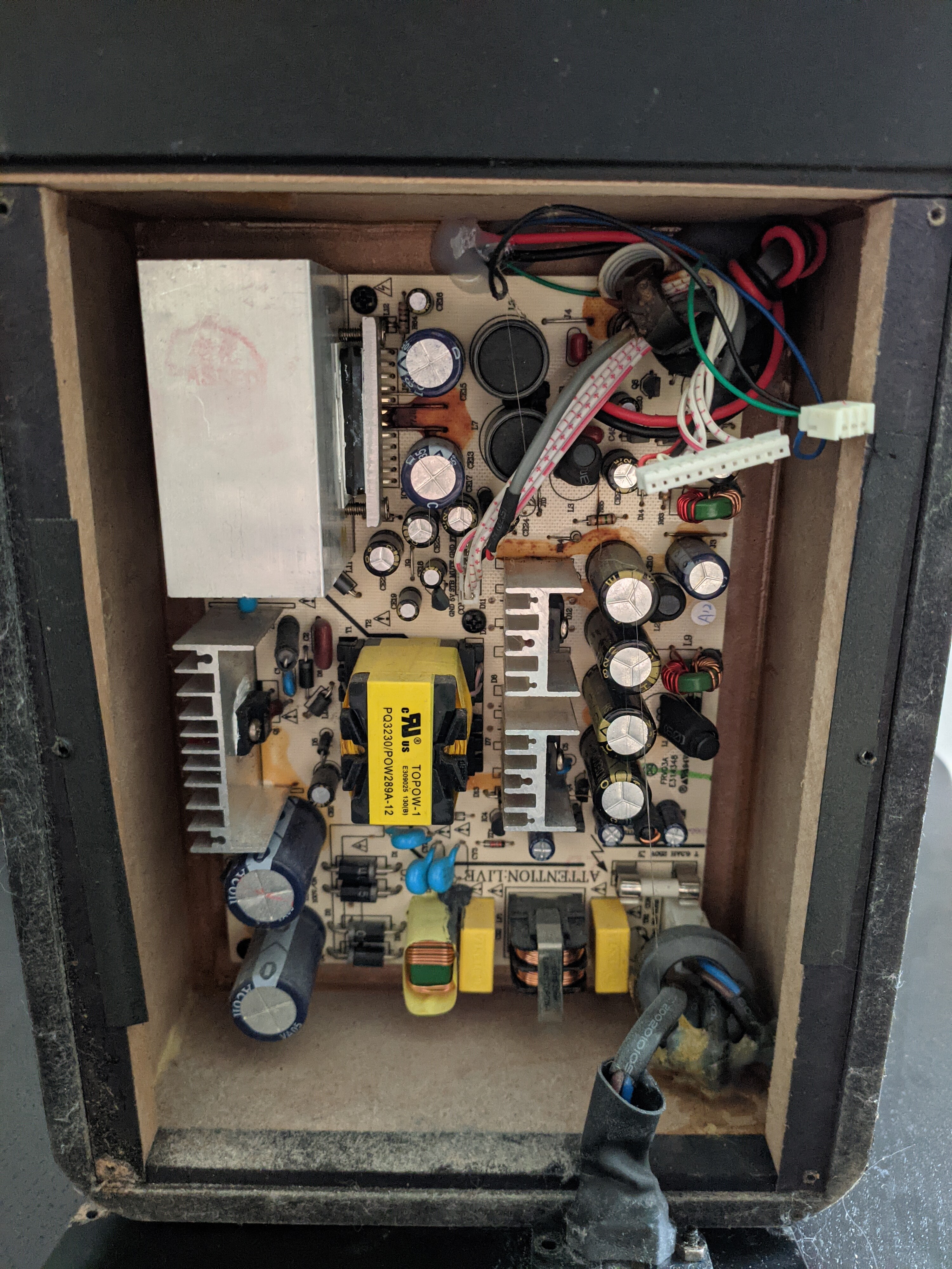
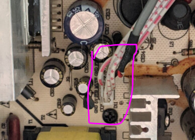
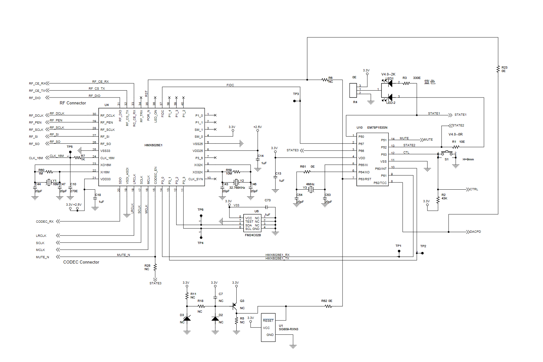
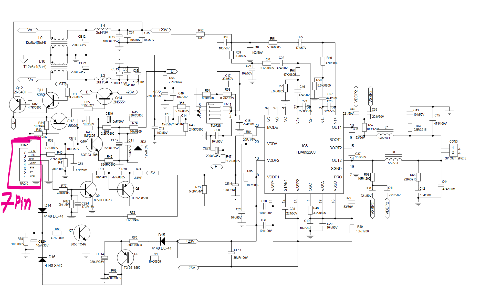
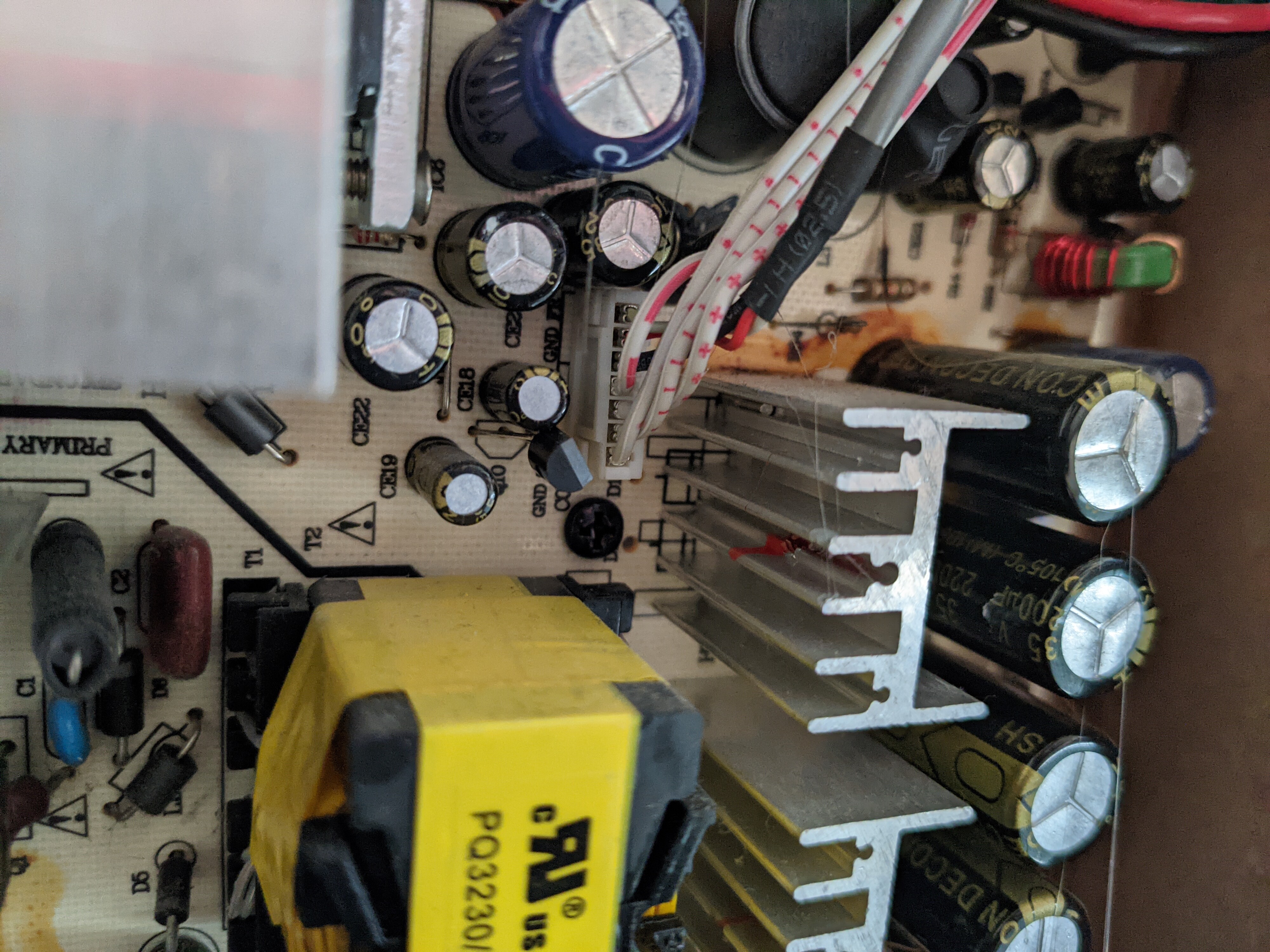
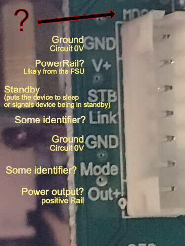
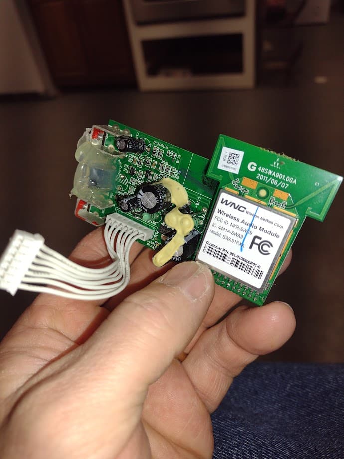
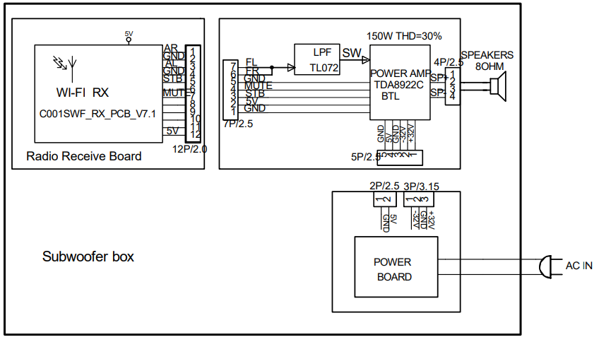
So, as the service manual clearly states, the Powerboard gets Left and Right audio in through a 7-pin connector (together with some control voltages).
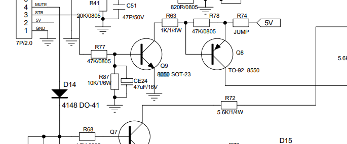
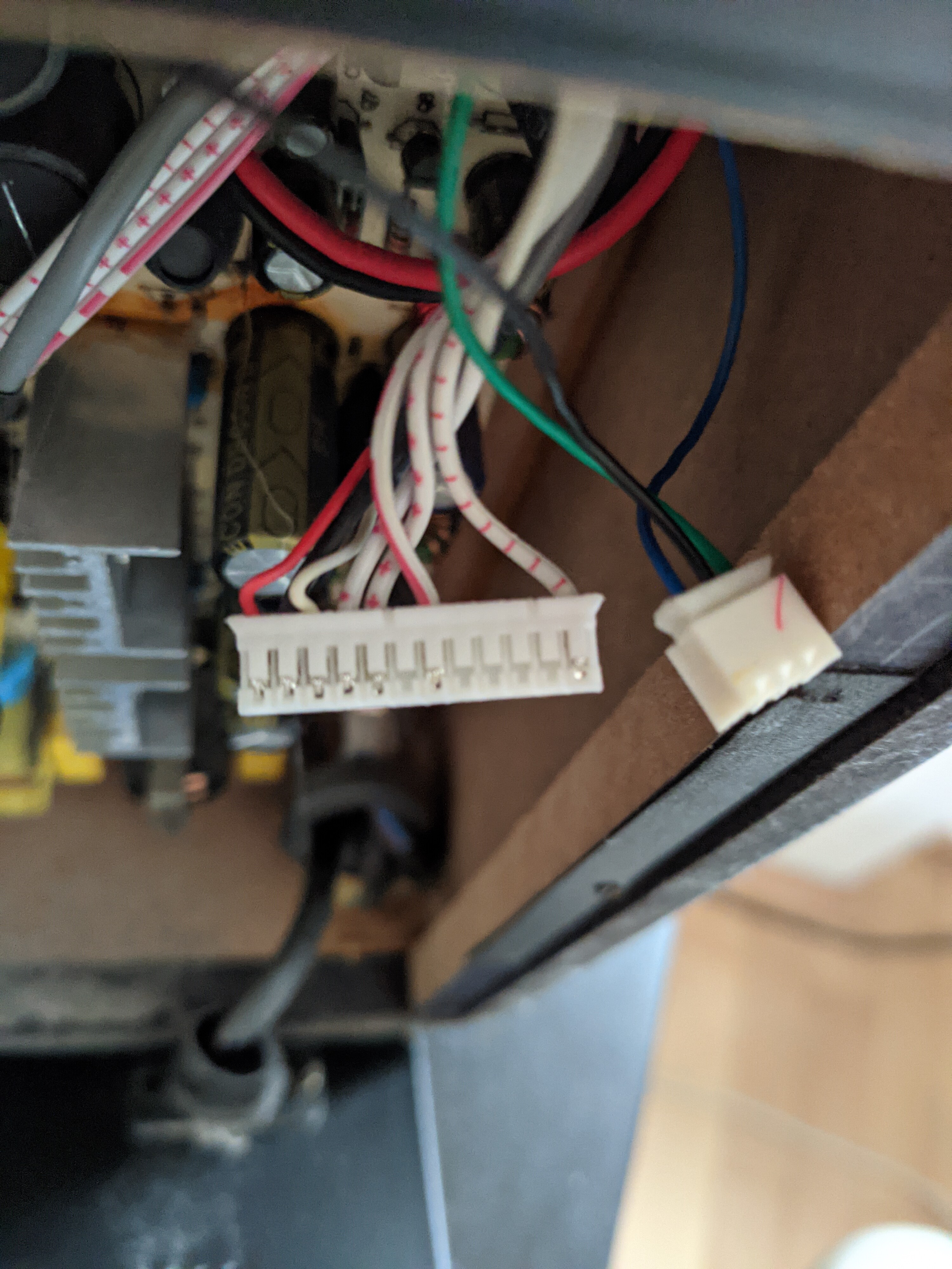
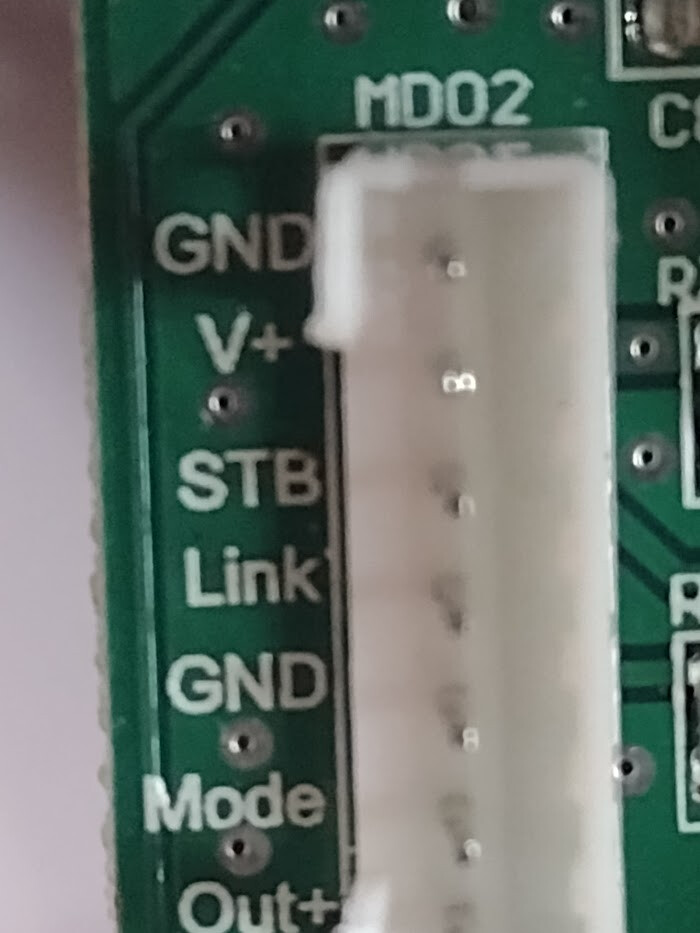
That connector is this one:
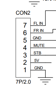
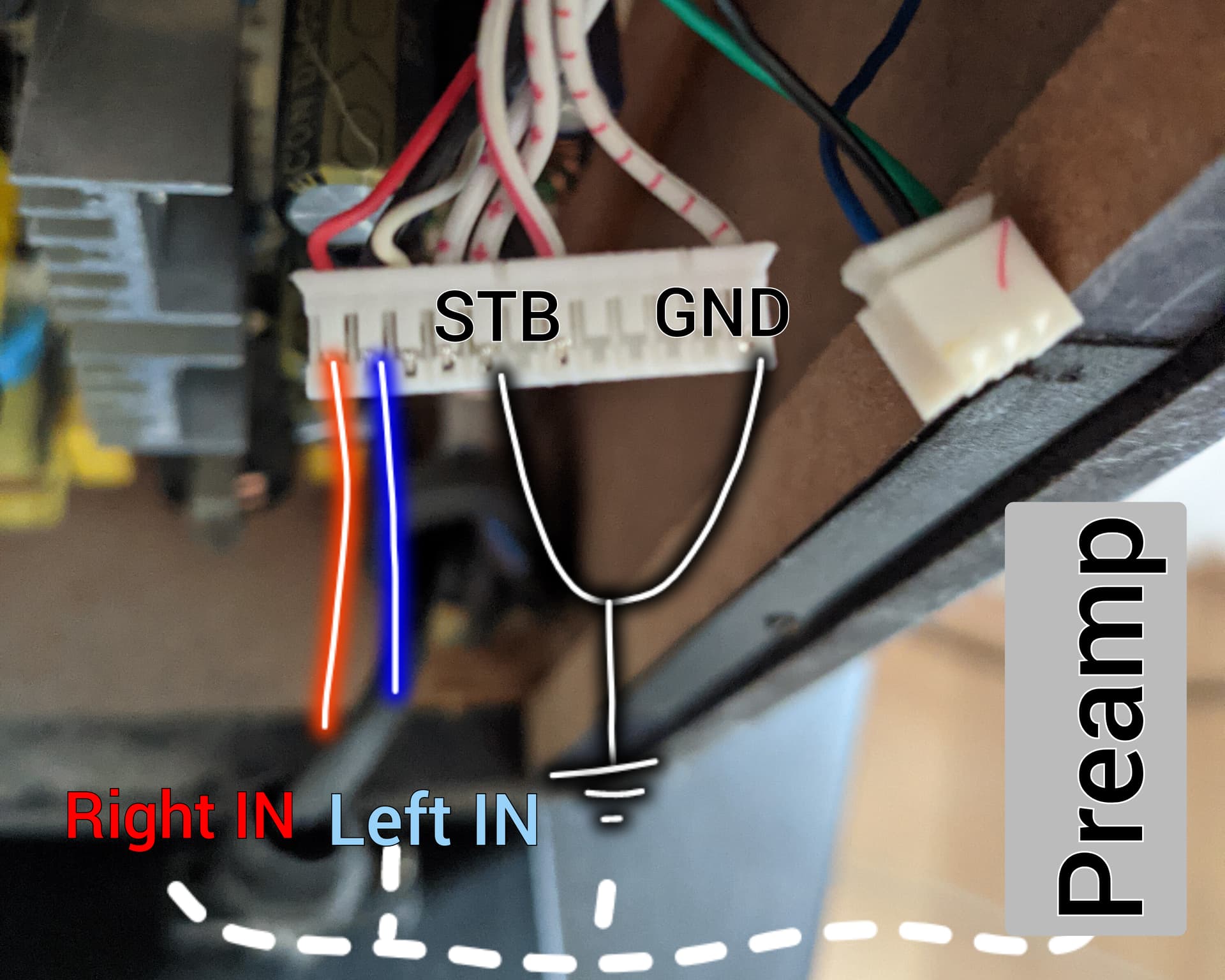
Pinout:
Leaves to figure out what state Standby (= STB) and Mute need to be in for it to operate ![]()
Yeah that’s the obvious thing. But, yeah, it’s fun to mod stuff. And it’d probably be a lot cheaper and better than no sub.
guess 0 and 0. I would imagine if the standby was 1 it would go into standby to save power and mute 1 would just mute the sound, but being prepared to unmute immediately. At least, that’s what common sense would tell me.
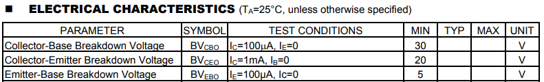
I meant what voltage. 3.3V? 5V? 12V?
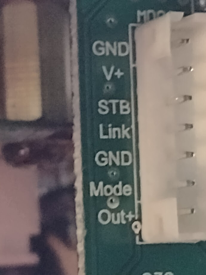
Oops. Well, I don’t know, maybe you can get that from the schematic for the radio board as that’s from where the other side of the cable to the 7-pin connector ends.
I would guess 3.3V, but without specs for “HMX6026E1”, hard to be certain.
Edit:
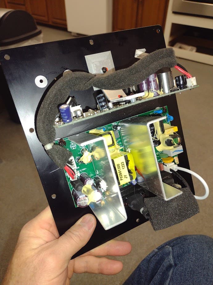
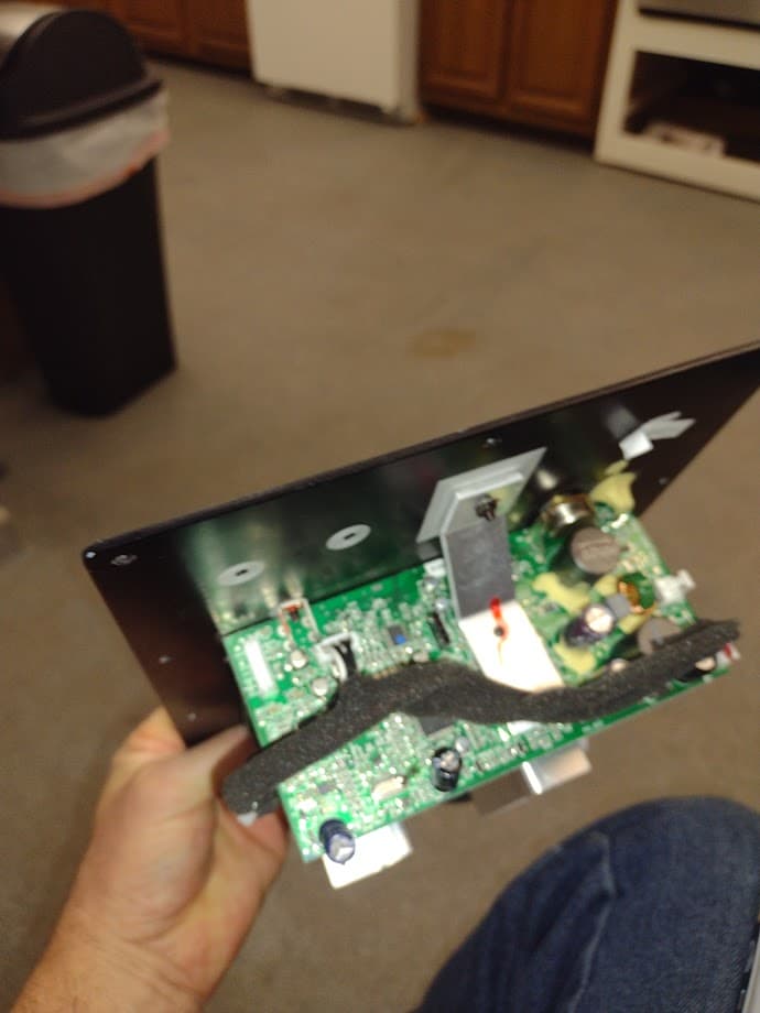
Took some more picks. Don’t know if that could help.
No datasheets to be found online, yeah, a bummer.
Any plan on how am I supposed to mod it then?
A few years ago I modified this sub, If memory serves, that’s how it worked.
It has a pretty powerful amp delivering around 120 watts to the speaker and working in the 30-120 Hz range.
In the context of the other boards shown, the header labeled MDO2 appears to be purely Power and control for the Powersupply.
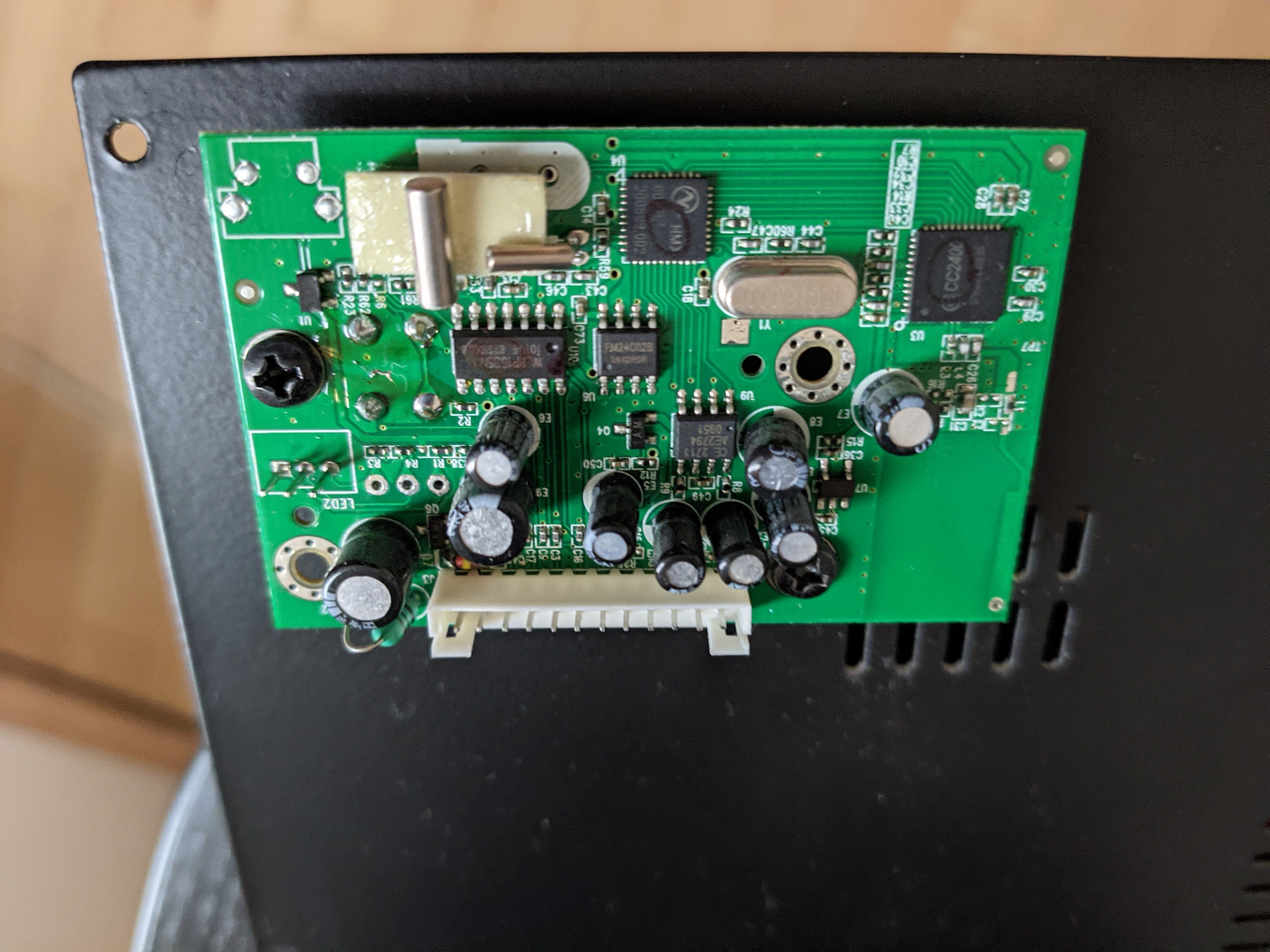
The board being held at a 90° angle from the panel is probably the amplifier and control board.
That was my assumption as well since the wireless card plugged into that assumed amp card via the 7-pin plug. Just don’t know how to suss out the proper inputs to the amp to feed the analog signal to.
Did you ever find the correct pinout? I have the same Radio board on an Energy subwoofer and would like to use in a different system.