Breakout connectors like that (also available for: Serial, USB, VGA, DVI, etc.) are super handy when troubleshooting or testing stuff.
Yes. Testing leads and connectors always are, it is the scopes, multimeters and other bench devices that get you ![]()
Breakout connectors like that (also available for: Serial, USB, VGA, DVI, etc.) are super handy when troubleshooting or testing stuff.
Yes. Testing leads and connectors always are, it is the scopes, multimeters and other bench devices that get you ![]()
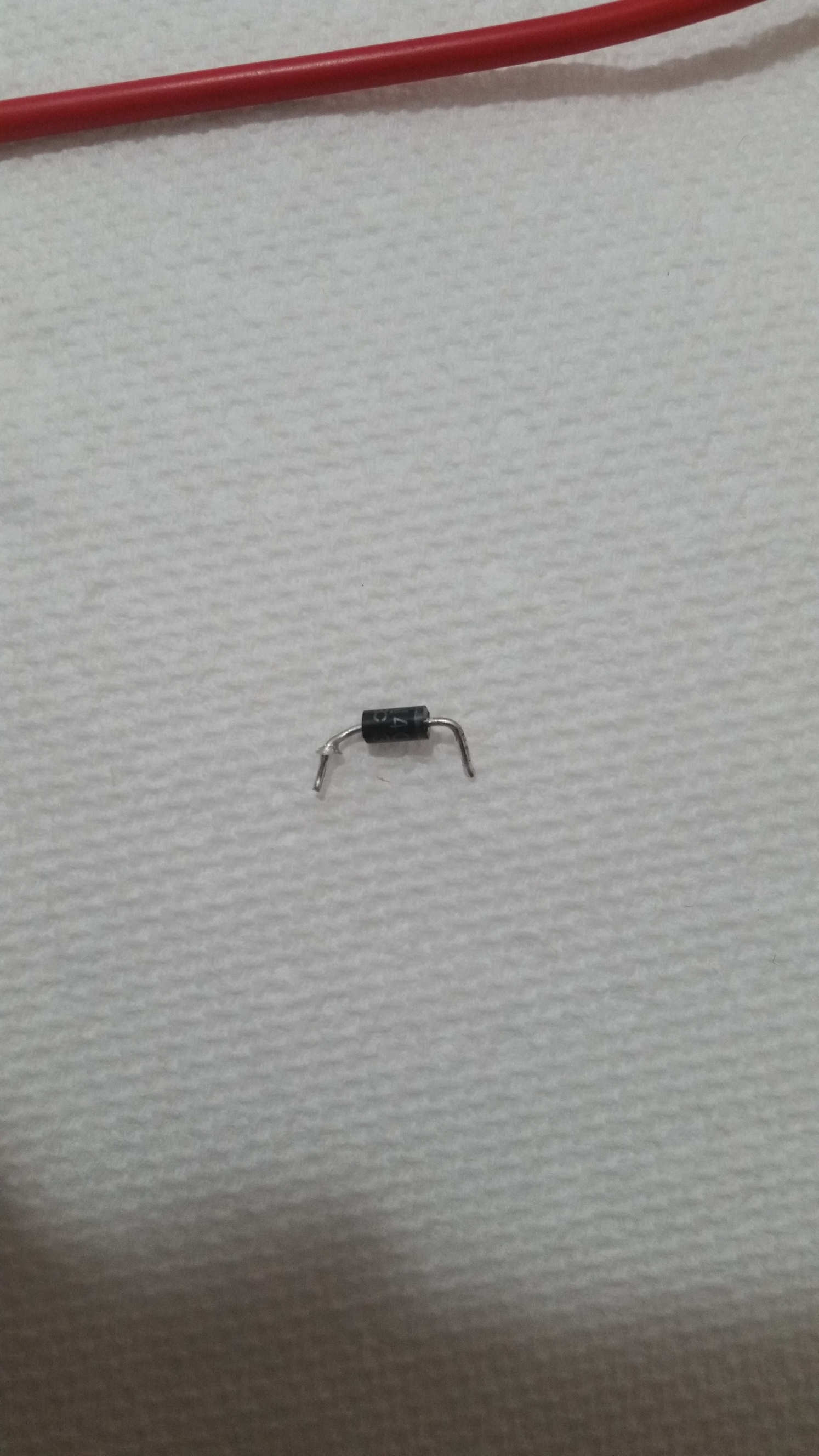
Ok, just removed one of the Diodes that the Meter said was open, thank God my theory about the circuit using those Diodes to block a circular path was right, the diode, on it’s own, is perfectly functioning, meaning @Polygonhell was correct and it was simply a temporary short, the 6.3mm to 3.5mm tip must have been bad/didn’t make enough contact and made a short.
Here’s a pic of the Diode:
I’m going to solder it back in, and just buy new fuses for Sunday, tell you if anything changes when the new fuses are in. Idk, it was probably just a fluke that it shorted.
Ok, just finished reassembling it, I took pics before hand so I knew how to place the Diode again, getting 12 fuses tomorrow, so since the amp uses 2 at a time, I guess that means I have 6 tried before I have to get more.
Still, seeing how easy it is to disassemble the amp, I might do some things to it once I can confirm it is working . . . Audiophile things . . . muahahahah.
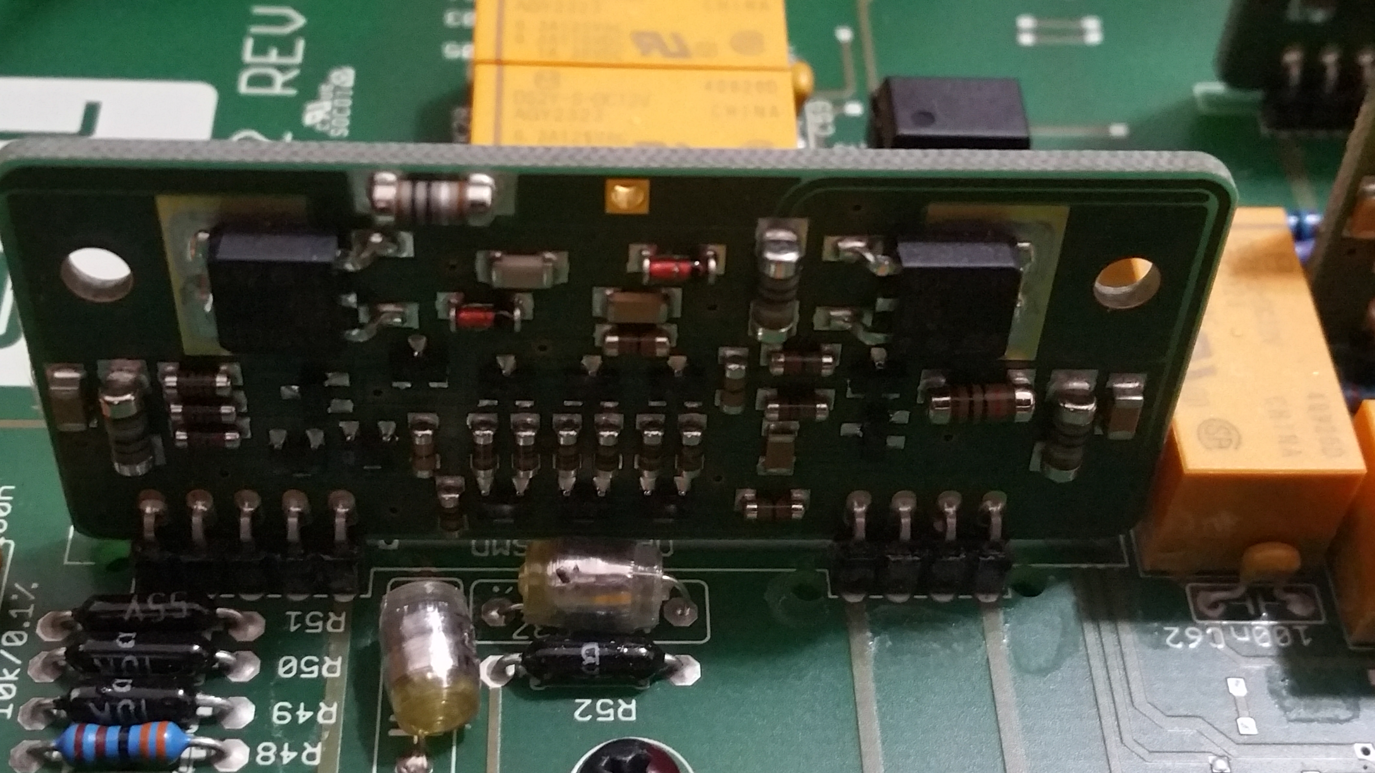
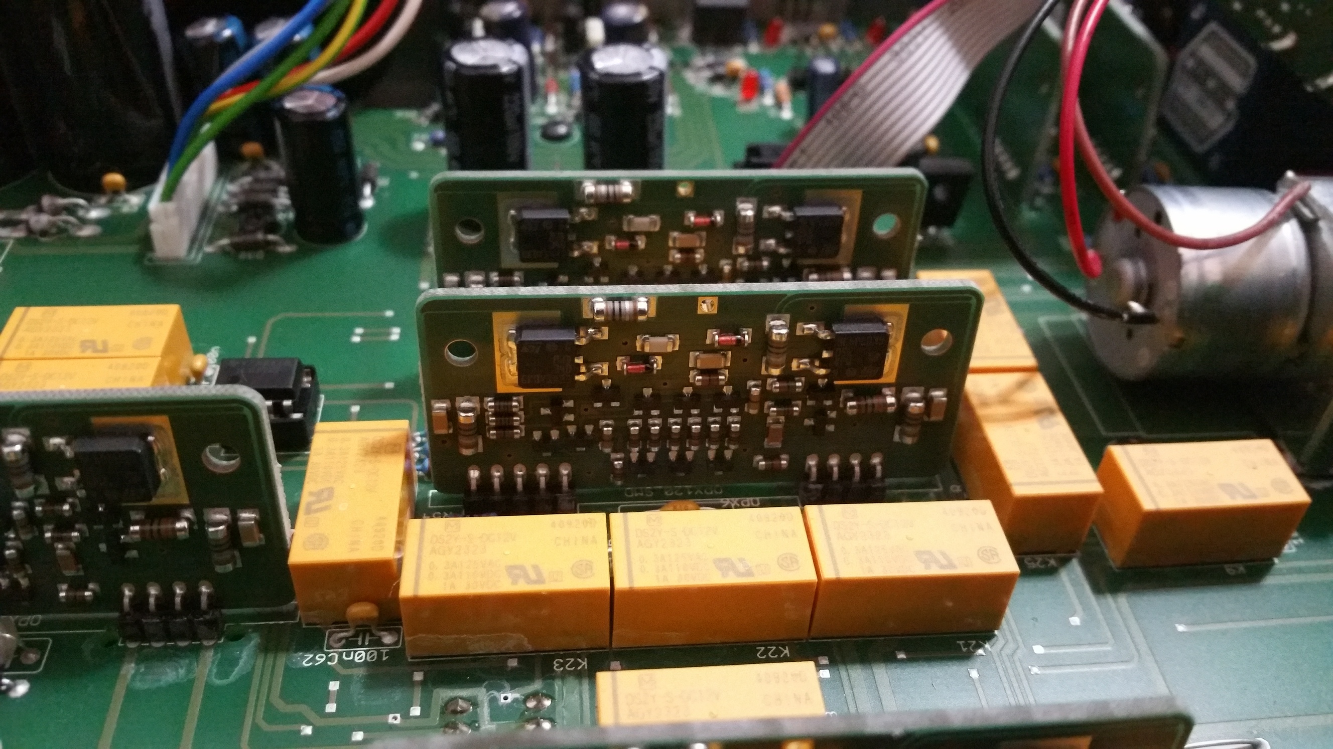
Also those vertical boards, they all seem to be identical in nature, each being numbered 37 with the same component layout, since I know tubes more than SS, I have no idea what function they hold in this circuit.
Also, how come 1A 250V slow blows cost 6 bucks for 6, when 3A 250V Fast Blows cost like, 3 bucks a pack of 250, idk, the world may never know . . .
They are like lego bricks, a module that can be used over and over. Makes manufacturing cheaper.
They also make laying out the PCB easier as you add a 3rd dimension to the layout.
Yeah that makes sense, but idk what they do, I guess help with Amplification, I’m guessing the act as a buffer because there are two that go directly to the Output of the Amp, idk tho.
Do you have a picture of one in detail?
Uhh let me check.
Nope, but I can take a pic of it, give me a minute.

Oh also, going to buy audiophile caps and resistors and Diodes and stuff when I’m 100% sure the amp has no issues, for the meme, who knows, may do something too, unlikely, bit it’s for the meme.
Oh also, If I can reverse engineer the vertical Boards, I can make Audiophile versions too, sell them for 600 dollars each, and put some audiophile brands on them, for the meme. I could probably figure out their circuit pattern by testing it and drawing a diagram, then find a way to make the boards and solder heavier duty stuff, and call it a day, rake in the cash with my Non-Inductive Silver Plated Balanced .0000069 THD Rake.
Evil, maybe, but I’ll be surrounded by too much audio stuff to hear the complaints, muahaha.
Jk tho. (Totally Jk).
Looks like power regulation, which is a sensible thing to have local to the components that need power. Cuts down on voltage droop over the tracks.
Another thing:
All of the components are surface mount (so no hand made here), then the board is attached with through hole (can be done by machines, is costly and slow though).
I have to question the use of MELF resistors though.
Ooo What are MELFs?
Also huh, interesting, makes sense though, don’t want to lose too much voltage in the circuit unless it’s on purpose.
Also yeah ik they’re surface mount, but it seems like a similar (more audiophile) board can be created, same values, beefier components, for the meme you know?
Metal electrode faces, cylindrical components with metal connectors on each end.
Has been arround longer than the rectangular SMD components.
Nothing special about them except they are harder to handle by machines.
Huh, just learned, the Phonitor doesn’t use Lead Solder, melting temp on the Diode was higher than Lead Solder, also, Lead Solder is shiner too than Lead Free, kinda weird since my solder was shinier than the rest of the board, does the Lead aspect affect resistance too much or does it not matter? I have lead free solder so I can just re-solder it with that.
Oh also, yes it is actually on the board, I can’t even get it to budge with a tweezer, and here isn’t any discoloration, only that it is shiny (I used Flux to make sure of that).
Oh also just of curiosity tested all the Red LEDs on the board, all work perfectly, so cute when they light up too.
Idk, just super anxious, hope the thing isn’t really broken, still gonna mod it tho.
No no-one manufactures with leaded solder anymore.
Huh, well makes sense, Lead is pretty unhealthy for you, but will it affect anything conductivity wise or does it not matter in this case? Idk, never had an issue with my tube amps when using Lead Free for joints and Lead for Boards, so idk.
Not really, the big issue with lead free solder is it doesn’t flow as well, there were issues with increased failure rates when it was first commonly used in manufacturing, but at this point it’s of no real relevance.
Oh ok, as long as it doesn’t affect the conductivity of the Diode I just soldered back in, then It’s all good then.