I’ve been looking for my next project to fill in my free time and DIY stepped attenuator caught my eyes. So far, I’ve been looking at several articles and YouTube videos and here are the ones that I think the most useful.
I think I have the basic tools, solder, breadboard, flux etc., but there are some that I need to buy, the rotary switch and the resistors.
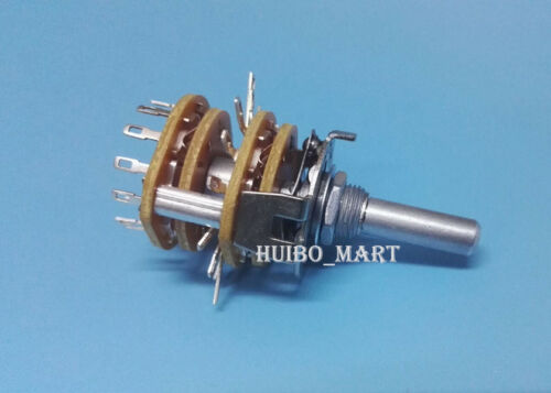
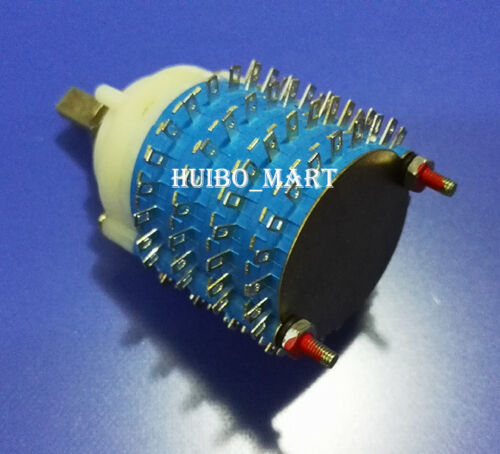
For the rotary switch, I decided to buy a six step rotary switch for practice and a 4 poles and 2 poles 24 steps for the actual use.
https://www.ebay.com/itm/1PC-2-Pole-6-step-Rotary-Switch-DIY-Attenuator-Volume-Potentiometer/273116127282
I’ll use any resistor that’s cheap and easy to get for the mean time.
I think I will do this project next month or so. If you have any experience, feel free to share your tips and tricks. Any suggestion and comments are welcome.
If this project is a success, I will proceed and do the relay switch one. I think it will be a little bit more tricky, but interesting nonetheless.
This is the only article that I’ve read.
I think that article is already really helpful. Right now, it feels doable, but we’ll see how it is.
Resistors matching is extremely important.
Hmmm, I was planning on buying 100 cheap resistors and match it myself. Should I buy a quality resistors instead?
If you match them is not really important if they are cheap or vishay militar grade resistor, but I strongly advice for a metal film type
1 Like
Ah okay, I’ll add it to my list. Thank you for the advice.
-
Interesting project idea
Please keep us posted on how this goes
-
You can get Metal Film (or Thin Film) Resistors down to 0.1% accuracy. While you pay a bit more compared to the “standard” 1% ones, you save yourself hours fiddling about with a test setup.
2b) Alternatively, you can use several higher value resistors in parallel. Say you want 10k, so you could use 4x 40k resistors.
When using uControllers, the relay one may be easier on the hardware front.
Instead of a uController, you could also divide voltage from an analog poti via Zener Diodes (or voltage dividers) to trigger relays from there. ← I have to double check feasibility of this! (Or take that as your own puzzle  )
)
1 Like
uController is pretty straight forwards, you’ll need a dual darlington array chip to drive the relays.
You can buy boards for this off the shelf or populated boards on Ebay for <$100.
1 Like
I’ll try my best to document my progress here. Hopefully other people can also learn with me.
This one will be a challenge for me, since my last experience with controllers was in my college. I think for now, I will prioritise the rotary switch version.
1 Like

