The VW Dieselgate of the audio world.
2 Likes
Nah, that would be to detect extended 1 kHz and then putting a 1 kHz tuned oscillator on the output (effectively removing any harmonics).
Also considered doing that…
Should I ever bring something to market, be assured I will do my best to make measurement peoples lives miserable.
3 Likes
Update 6
Blessed be thermal cut out!
In other words: No, skipping the bread-board prototype does not save time.
The longer story:
I wanted a virtual ground to circumvent me running after my own tail later with a ground loop causing mayham. The theory is solid. Have a positive rail and Negative rail, cut in half for virtual Ground.
As power draw varies depending on load, the resistors providing vGround need to vary. Easiest way to do that is with a pair of linear regulators.
My thinking here was instead of creating a positive rail before the vGround-circuit, I could do that after it. I was WRONG!
My shortcutted vGround is a very efficient 24W heater. I found that out by burning myself on a rather unhappy Linear Regulator in thermal-cutout (happens at >150°C / 300°F). Whoops! ![]()
The Fix:
Easiest way would be to bypass the vGround circuit. That would open the gates for ground loop issues and the fun that entails.
The “hackjob” would be to rewire the LM317 (= adjustable regulator) to be before the vGround circuit. This hack holds the possibility of not working.
Optimal solution is to man up and build the real deal, voltage reference, protection diodes, etc. The thing I wanted to avoid…
As this was meant as an easy starter, I will probably just kick the vGround circuit off the board and hope for the best.
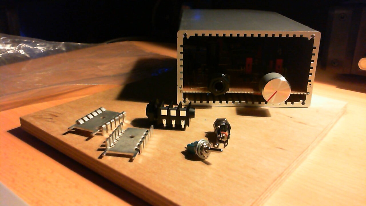
20 Solder joints, 5 internal bits, 10 screws and drilling 5 holes away from seeing if this works
6 Likes
A few random questions on the schematic from Update 5. Some of it might just be because the schematic is outdated.
Where does the NE5532 power come from? I didn’t see the connections for it in the schematic (maybe I missed something). The NE5532 requires a positive and negative supply unlike the LM380N.
The LM380N’s output voltage is supposed to be centered at 1/2 of the supply voltage but the output connector common terminal is connected to GND. In the datasheet, the example circuits use a coupling capacitor to get rid of the DC offset. How does it work in this circuit?
The LM380’s voltage gain is 50 which seems like it might be too much (considering that the NE5532 also provides some gain).
Magic.
Don’t know what happened to the rail labels. When done and working, I will update accordingly.
That is to be tested. All of this is a test bed.
In case it does not work, I have a selection of caps on hand to use.
NE5532 is unity gain stable, so I could configure that. I also have the option to bodge in a voltage divider at the InputL and InputR resistors.
As I document this project on two different forums, I may have missed the note of the NE5532 being placeholder for an OP275. I should also have another NJM4580 somewhere.
Note on split-rail: That would not be a problem (or a smaller one) if my oversimplified vGround would have worked.
To make this worse, before this project I had no need for multi-rail power, as such, my bench supply is single rail (and tops out at 15V-ish). So no bread-board sanity check either.
1 Like
Minor Update
This is the schematic of what I currently have. Will give this the full sanity check, measurement check and when all goes well, a first listen.
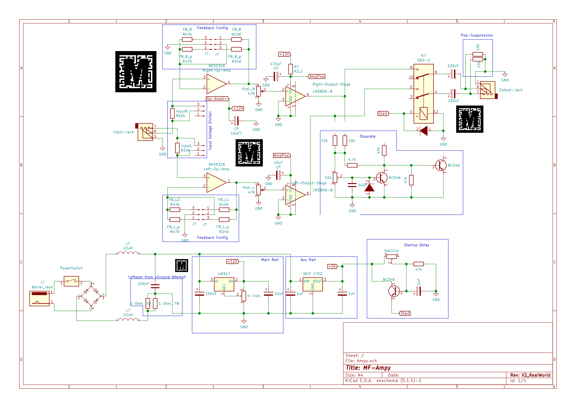
A few notes:
-
The Input voltage divider as I implemented it is just a pin-header to let me hook various resistors between the 20k Ohm and Ground. As drawn, it is NOT what it says on the schematic!
-
The “Pop-Surpressor” may need different resistors
-
The Label on the regulator providing the Aux-Rail is Bogus
-
You can totaly “Oopsie” an astronomical gain on the input stage
4 Likes
Really curious to see your progress on this project. Very cool to see how thing go from the ground up.
Two questions:
-
I may have lost the read in the logs, but have you given up the class H idea? I’m legit not seeing where the 5V rail goes.
-
For the pop circuit, why not use relay or transistor for soft start-up?
And I’m very much interested in getting a kit when it’s ready. 
It is on hold until I figure out some important aspects I was not aware could be a problem.
The 5V Rail used to power the DC-detection circuit (marked obsolete), now it just feeds through a start up delay into the relay.
Don’t need to switch off on DC when there are capacitors to only couple AC ![]()
Those two resistors are there to get the output facing side of the capacitors into a known state. Else they are “floating” with what ever voltage happens to be in there when you unplugged the headphone.
Completely understand, sometimes is better to take a step back to a simpler thing before going to a more complex territory.
I see, it makes sense with the relay having the startup delay. My only concern would be if these resistors are somehow messing with the output impedance of the amplifier, maybe getting part of the power transfer to them. Although, considering how headphones are usually within the 100Ohm range, the hundred times bigger resistor should not make a significant difference.
Did you simulate this circuit? If so, what software are you using?
The resistors are in parallel with the headphone. As they are 10k Ohm and most headphones are 600 Ohm or less (= have 16 times less resistance), I am not expecting them to make a difference.
Kinda sorta? I am more hands-on when tinkering with electronics.
For simulations, I use LTspice. I am definitely not qualified to explain how to use it though.