This thread will server as a “blog” of sorts on my journey to planning and building a discrete headphone amplifier.
Concept
There are various amplifier classes, some suited to audio applications, others not so much.
Design Corner Stones:
(These should be nailed down at some point)
Switchable Class AB/H - At the core of a Class H amp design resides a Class AB amp. As the market is flooded with discrete or integrated AB headphone amps. I do not (= can not) compete with those.
Fully Discrete - As this is a learning project first, potential kit/product second, I want to be able to stick a probe on every leg and observer what is happening.
No direct Grid feed - May sound odd, but an off the shelf wall adapter makes certification easier.
Do not trust the Power - Surges, EMI, switching noise, etc. will be filtered out before the internal linear supply gets to do its job. The aim is to build something that does not care if there is a pair of car batteries or a thousand dollar precision source meter supplying power.
Hurdles
(There are always more of these, in decending order of importance)
Certification - When I sell this as a kit with plans, I only need to declare CE-conformity and I am good. Pre-built units would need further certifications like “TÜV” or FCC (I could use some expert knowledge on how exactly FCC conformity works).
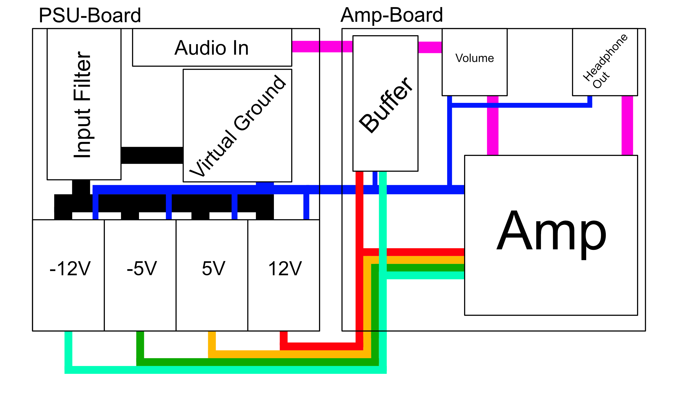
The PSU - I need 4 rails for this to work correctly in Class H mode. As I painted myself into a corner with the external wall adapter criteria, I will have to create a so called virtual ground before the main PSU can generate the 12V, 5V, -5V and -12V rail. These voltages are arbitrary.
This virtual ground either result in a device that always has ground loop issues or a device that never has ground loop issues. I lack the experience to tell which one of the two.
Just one for the “meaningless feature”-list is that I will either use a “precision” zener diode or reference voltage source.
Input Impedance - More of a soft goal, but I want to present an input impedance of at least 10k Ohm.
– The cheap route would be a 10k resistor before the main volume pot.
– Another way would be to have an Op-Amp with unity gain sense from a 50k resistance. Kind of breaks my “fully discrete”-goal. I could get an integrated AB-amp chip and run it into a voltage divider to get it to unity gain.
– [Non-Option] Let the user deal with “whatever” impedance.
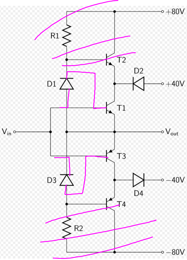
Mode Switching - To reconfigure from AB to H mode, I need to cut out the additional transistors and put the Diodes directly in front of the inner transistors. As I do not want the user to flip multiple switches or place jumpers, I need bi-stable relays. In doing so, I need to prevent reverse-biasing transistors (bad!) or shorting supply rails (not good, but LDOs current-limit anyway)
Rough sketch of Class H to AB switch:
I can not just disconnect the high voltage supply rails because Class B would be BAD (then again, being the worlds only Class AB/B/H headphone amp might be cool?)
One upside of having all these relays is that I could present the user with a nice 4-position switch to select B, AB (low voltage), AB (high voltage) and H.
Volume Pot - I put several minutes of thought () into this, looked at a grand total of 4 spec sheets and then decided I don’t want stepped attenuators, digi-pots or exotic solutions. Current idea is to have a pair of multi-turn pots connected via timing belt (I could not find one with two channels). The idea here is to get out of the channel imbalance while there is nothing audible going on while retaining the fine controll of an analog pot.
Thoughts
Cost should be manageable. I have not compiled a BOM, I expect less than 200€ though.
Size wise, it should fit on a pair of “normal” sized proto boards, one for the PSU, one for the Amp itself. That is okay for prototyping, for kits or products, not so much. Form factor could either be “box” (think Vioelectric V280) or “flat unit” (think RebelAmp).
Why?
Because I am a tinkerer. And because all the people using speaker amps for power-demanding headphones makes me slightly irritated.
Arbitrary decision on my part.
Class A in particular is difficult to implement correctly due to the 360° of conducting angle of the switching elements. Class AB is only 180° making component selection easier.
I put in the better part of 3 hours to get the PSU-PCB set up. The two biggest problems were fitting everything on it and minimizing the number of jumpers.
Small annoyance is that out of all the component producers, just two have good options to filter for application. Made researching this a lot less fun that it could have been.
A few changes have been made to the initial design goals:
Volume Controll will be just a standard poti (Alps RK27112 to be exact)
Fully Discrete is no longer 100% true as there will be two AD SSM 2141’s acting as input buffers. Way superior to any Op-Amp based solution, a “shame” in the sense I no longer tick the “fully discrete” feature box.
Also: In b4 some one tries to replace the two 8-pin chips with Op-Amps. Those two are definetly NOT pin compatible.
XLR (on input and output) got kicked out because of space limitations. The 160 x 200mm board size is down to available cases. I could add a daughter board, or eventuall customers could buy TRS to XRL adapters
General something something: This device may run surprisingly warm. Leakage currents should be pretty low per transistor, I am running a lot of Linear Regulators (2+4 in the PSU) and big Transistors (4 in the Amp) though.
So the “I want an Aluminium-Case”-Decision is 80% functionality driven.
Edit: Let the AutoRouting do its thing for 200 rounds. Either my component layout is absolute shite, or, hopefully, the AutoRoute in Fritzing is reaching its limits. Might have to re-create the part in KiCAD instead.
Because I am NOT routing that manually!
Note
If you are a manufacturer of hifi gear, feel free to give this type of amp a shot yourself. A properly trained electronics engineer should have the first functional prototype up and running in ~6 hours.
I will not release any schematics, will also not pursue any patent/copyright shenanigans either (too expensive).
The “design changes”-tier issues:
I think, more hope, I figured out how to lay out the Amplifier Board. Instead of doing a 12-relay dance to switch from AB to H (or B), I am just going to disconnect power to the “outer” transistors and only do some minor relay-switching.
There is a little twist concerning biasing that showed up as a potential problem while running simulations on the circuit, details…
As this device might run warm, I was thinking about a way to have a thermal cut out. That is not happening due to space limitations.
So instead, I will just get 105°C rated capacitors instead of 85°C rated ones. Works for video cards
Now the Big Issues: Amplifier Board:
I have some educated guesses on what resistor values in the amplifier have to be. I have tried to simulate that circuit, which told me surprisingly little about the circuit.
For those wondering why I need resistors in the signal path: I think I want to stay in the saturation region of the transistors and not slip into the active region.
AFAIK, this “danger zone” (in AB-mode) is at 1V. In H-mode, reaching this region will probably kick the “outer” transistors into high gear. Because you know, diodes on the output controll the outer transistors. So this “danger zone” is even worse.
To have some safety between 24 angry volts at 2A (= 48W), I will include a voltage divider after the amplifier. This means my output impedance will be 10 or 120 Ohm (switchable?). So your “gain control” is not fucking with any feedback (or lack there off), but changing how protected you are from the wrath of the transistors.
PSU-board:
As I currently do not have access to my universities electronics labs, I have the following options:
Ask random strangers to let me into their lab. Or for them to replicate the board and test it.
Price: Shame and/or Embarrassment
Find people willing to give me about 1500€ to buy test equipment.
At this point, why stop here?
Why settle for “budget” gear?
Go for gold (literally) and buy a full on GW-Instek PEL-2002A and a pair of PEL-2020A for a combined 4,065.02€!
Price: Setting up a GoFundMe, so basically Option 1.
DIY some resistors, switches and banana plugs into a fancy resistor ladder. Maybe a pair of analog gauges to give me an instant “top or flop” result.
Price: ~120€ in Material and the time to assemble it
Edit: I could also get myself some shunt resistors (and heatsinks for them) and loan a friends oscilloscope. That would give me a pretty high resolution readout of currents. Question remains how I test ripple stability…
Don’t test it, just “Hope it works”
“Not my Problem” Let the customer figure it out! Just supply the Amp-board and a breakout cable.
This has the advantage of giving me an excuse to buy a bigger bench power supply
Minor Problem:
My bench PSU tops out at 15V (and 1.5A). My current design asks for 24V@2A. It is not that I distrust Meanwell. I used their supplies for some projects in the past and intend to use a [email protected] power brick for this too. I just don’t think it is good to test circuits on a PSU that is not designed to be randomly shorted out.
So I need to either get a bench PSU on loan or buy myself a bigger one.
Super Minor update:
Mostly a correction honestly.
It was brought to my attention on an electronics forum that my design is in fact Class G, not Class H.
Welp.
Can’t win when the initial plan is Garbage
To make my life a lot easier, I decided to kick out the automatic reconfiguration using relays. Instead I make a half-way step.
The internal structure will be a Class-AB setup with the option to power on the outer Class-G setup.
"Gain Switch"
Will not be “Gain”. Input Gain will always be unity. This may come back to bite me. I am going to burn this bridge now.
What I want to make adjustable is the total impedance presented to the amplification stage. Nothing fancy, just a voltage divider.
Chasing output impedance down to 0 is probably going to result in tears, and the Beyerdynamic A-20 tells me 100 Ohm for higher impedance headphones can work.
So 10 Ohm in “low” mode and 120 Ohm in “high” mode?
TL;DR of this here: No Gain, but an “Impedance Match” of sorts.
The (dreaded) PSU testing
The super-cheap option that did not even cross my mind:
4 Power resistors, 2x 24 Ohm and 2x 10 Ohm
That way all rails run at half load and maxes out the combined power budget of the device (and 80% of the power brick).
Should be alright, right?
I will also likely throw some more filtering on the board as I am currently running into noise issues in a different project.
Expect the first actuall happening mid February, starting with the PSU board.
no on/off switch
→ Already fixed, then again, the switch is more part of the case than off the circuit board
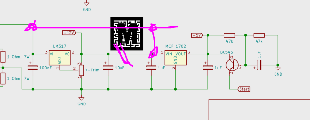
the start-up delay will likely never start (because the resistors are both 47k Ohm)
the input stage Op-Amp needs some resistors before it to prevent external “whoopsies” from affecting it too much. Not sure if I add some.
the feedback circuit for the input-stage is complete bollocks
For the NE5532 I plan to use as test-dummy in the input stage, the datasheet specifies 36k Ohm resistors in the feedback circuit, recommends below 6k Ohm to optimize for noise.
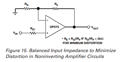
For the fancy OP275 I plan to replace it with for use, the spec sheet says this:
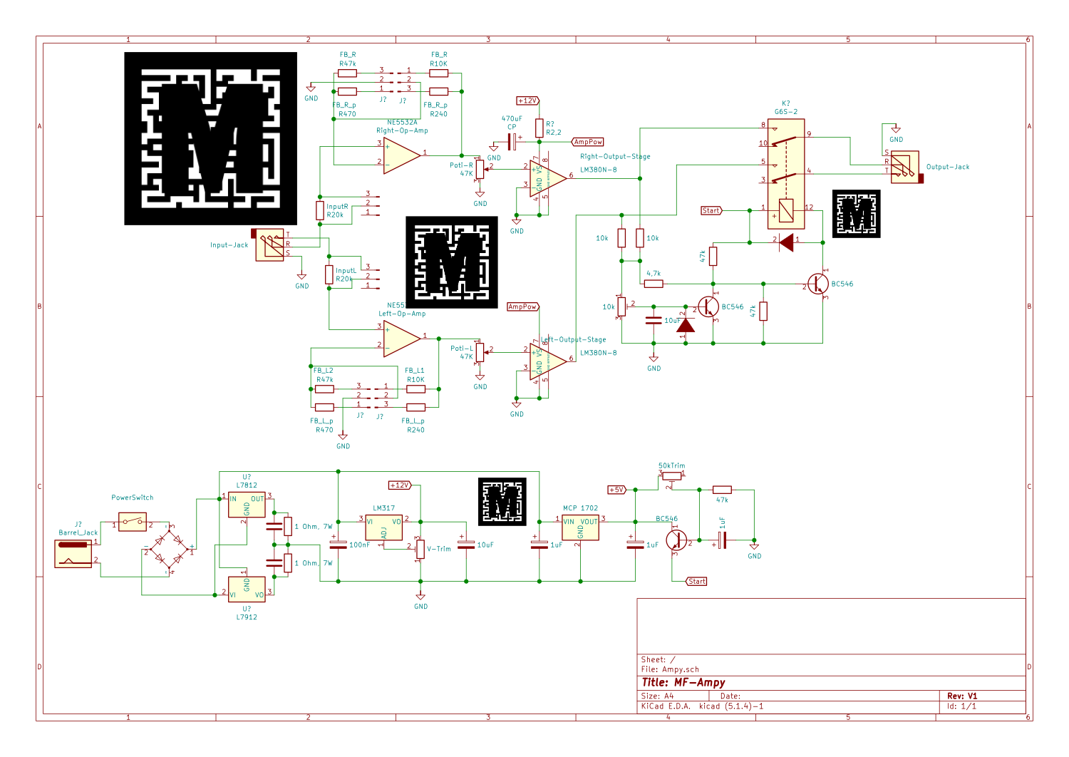
↑ Since exporting the above schematic, some more tweaks happened. One is to remove the whoopsie, the other is two include a pair of inductors on the power input
After this is built, tested and tweaked, I will post a final schematic.
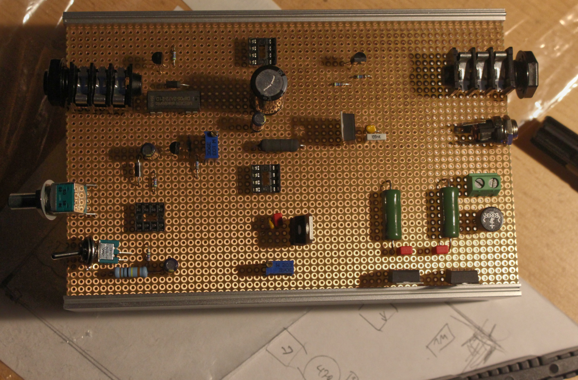
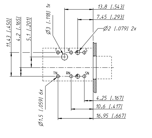
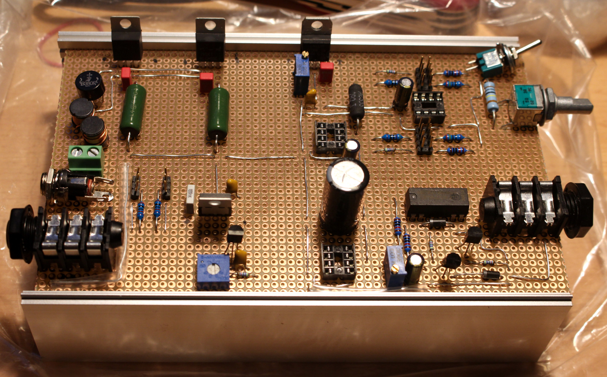
Started work on the proto-board. Got the mount points for the potentiometer and one of the 6.3mm jacks carved out.
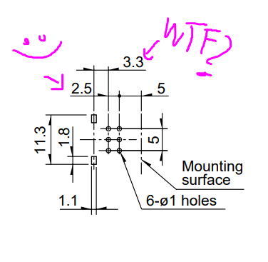
The Poti I got has 2.54mm grid size, which is great since the proto-board I have is the same. Except the “stability”-tongues, wich are just random. WTF Alps!? Why not 2.5 or 5mm spacing? WHY 3.3mm?!
I also found the heatsinks that went missing, too bad I ordered new (and different ones) in the meantime. These will be soldered into the board with the regulators screwed to it for stability (can’t have a TO-220 package flapping in the breeze, can we?)
Top-Side layout and routing mostly done. The only questionable decision is the black resistor on the right jumping over Gnd and Pwr for the input Op-Amp.
Completly missing are paths for audio
Sort of. I went with 6.3mm TRS on the input because I have spare cables to hook it up with.
And since it is unbalanced anyway, this saves me from having to drill one hole in the back panel. (As in 2 now VS 3 had I gone with RCA)
Also: $10 per piece? Seriously?
I could buy 28 of the jacks I used here (Neutrik NR-J6HF) for that money.
I have been thinking about putting in a notch filter to specifically filter out 1 kHz just to fuck with everyone trying to measure it.
One small notch in the spectrum missing should be mostly inaudible, but measurements are just worthless
 ) into this, looked at a grand total of 4 spec sheets and then decided I don’t want stepped attenuators, digi-pots or exotic solutions. Current idea is to have a pair of multi-turn pots connected via timing belt (I could not find one with two channels). The idea here is to get out of the channel imbalance while there is nothing audible going on while retaining the fine controll of an analog pot.