Before I get started on my HP50 balanced mod guide I’d like to warn people that this does change the HP50’s sound. If you use your HP50 out of a phone or laptop the headphones will become more amp/dac picky. The sound on a technical level is still improved, but poorly recorded music or peaky sound will become more apparent. I believe the tonality is the same, but since the headphones become more revealing/detailed bad masterings or youtube recordings will likely stick out. Note if you’re not comfortable soldering, get used to it before attempting this mod. This is a fairly trivial solder job, but holding the iron too long on the driver contacts can destroy the driver.
You will need:
-
Soldering Iron/Soldering station
-
Solder
-
Screw driver set
-
Multi meter is not required, but strongly recommended
-
New wire. I strongly recommend Mogami 2534. I’ve experimented with lots of cheap wire, like cat6e, which was the worst, to a dead MacBook charging cable. Just save yourself the hassle and get some Mogami 2534 for less than $2. We need less than 5 inches of it. Since there are 4 wires in the cable, 5 inches is more than enough for both drivers.
The main benefit of this mod is changing how well the headphones scale. I don’t think anyone would describe the stock HP50 as a great scaling headphone. In stock form the instrument separation isn’t the best, and the bass impact or slam is kind of weak. Sound stage improves as well, that is for a closed back.
With that said, the first step is to remove the pads. The headphones should look like this:

We’re going to remove the 4 screws visible.
Carefully lift the plastic cover, but don’t pull it away as the driver is still wired to the rest of the housing. Put the foam aside, we’ll need it for reassembly.

Next, we’re going to remove the second plastic cover. It is not screwed in. I used a flat head screw driver to gently lift it from the hole as shown.

Unscrew the remaining 4 screws. Apologies for the dirty headphones.

At this point, since mine are already modded yours should look different. There is a wire that comes out from the head band. We won’t need this anymore. If you aren’t interested in reversing this mod, you can simply cut the wire as I have.

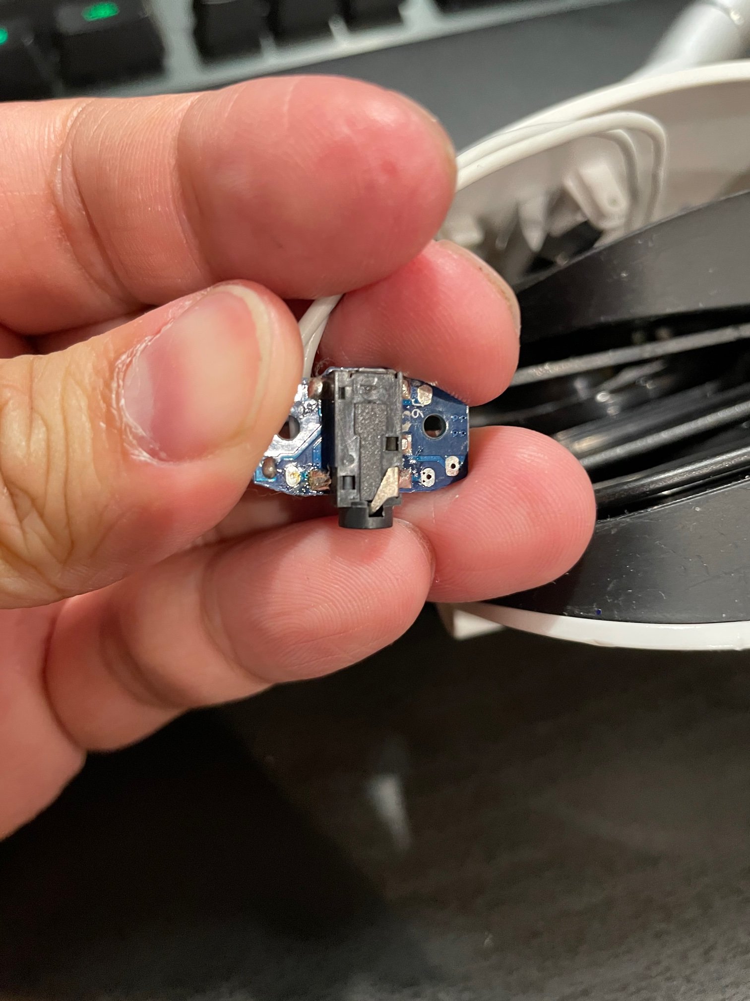
We’re going to unscrew the PCB next. You can cut or better yet, desolder and of the existing wire. We don’t want any of the old wire anymore. We won’t even be using any of the old solder points on the PCB. We will wire directly to the legs of the female 3.5mm receptacle.
Measure out the length of wire required for the job, strip the jacket and tin in the ends. If you don’t know how to do this, please look up a few youtube videos as that is out of the scope of this guide.
Before we start soldering REMEMBER not to place your soldering iron on the contacts of the driver for too long!!! I use a Hakko FX-888 soldering station. I set the temperature to 345.
A few key thing to remember
-
Tin the wire first (i.e. put solder on the wire with an iron before you solder it to the driver)
-
Keep track of which wire is going to which contact of the driver/PCB. We don’t want to screw with the phase/polarity.
-
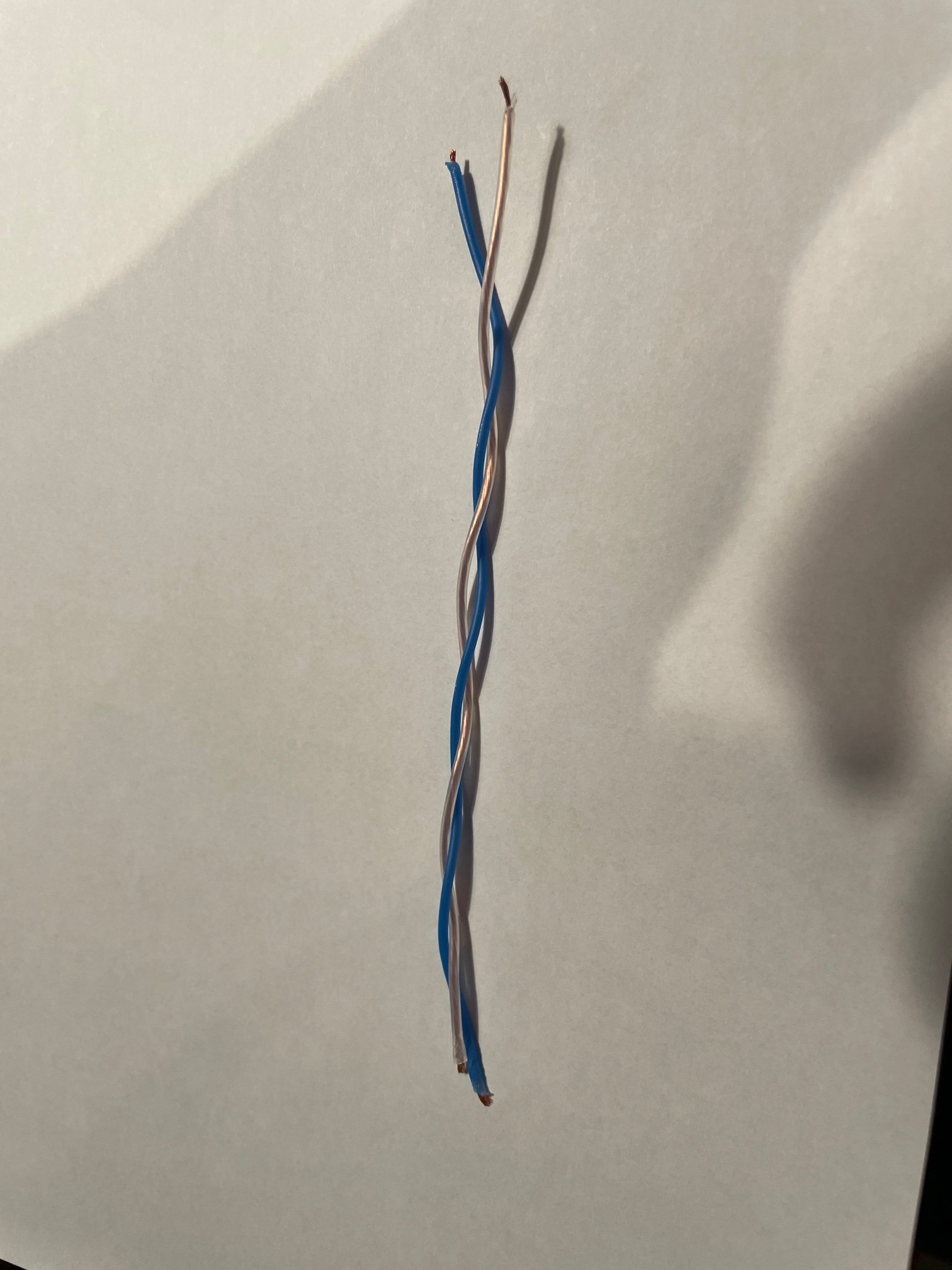
In the pictures below, the white wire is L+/R+ and the blue wire is L-/R-
-
Try to keep the wires as a twisted pair as pictured
-
Make sure you put the cable through all the different plastic housings in the correct order and orientation before you solder both ends of the wire.


If you’re using Mogami 2534 just follow were I soldered the blue and white contacts respectively. After the soldering is done, make sure the contacts are good with a multi meter, then reassemble. Now would be a good time to clean the inside of the housing before reassembly. Do the same to the next cup, or A/B each side and see if you can hear a difference. Use a headphone amp/dac and appreciate how much better the headphones scale now.
Good luck!