Here is a project I completed several months ago that really worked out well. A friend over in France had this design in his head and shared over at DIY Audio, TI was coming out with specific op amps designed for Headphone amplifiers! So with this really niche market I was very curious to how these new headphone targeted op amps would work in a headphone amplifier…
Usually with these new IC’s you wait for months before OEM vendors offer a product with the new technology, Schitt and THX use some of these op amps in this series of new ic’s in some of there new offerings…so to get ahead of this I decided to build this friends design…(back then I had NO idea what Schit or THX was up to).
A neat thing is one of TI’s design engineers that designed this specific op amp joined in the discussion several times watching us noobs using his “baby”…
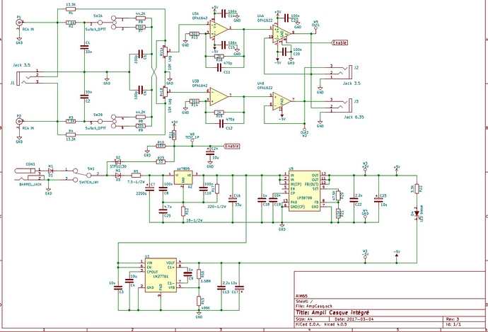
Chris’s “Ampli Casque Integre” Schematic:
The op amp in particular is the TI OPA1622. At the time I built “Chris’s” design there was not a commercial product with this chip in it…and the size of the chip was very, very small compared to existing DIY parts we are used to. On other DIY projects like my AGDR ODA I got to solder really small 805 parts. This amp has even smaller parts and they can not be soldered with a conventional soldering iron. Their are “leadless” QFN parts.
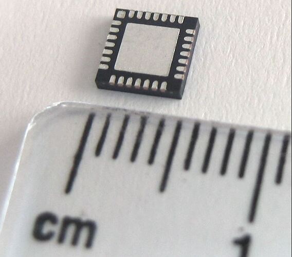
Whats a QFN: Quad Flat No-leads package, they have no leads or pins like previous op amps, they are flat and you have to use a different method of soldering them to a pcb. Commercially they use solder pots, re-flow ovens etc to get these devices to attach properly. There is a thermal profile as well that you need to be aware of, too much heat for too long can destroy these small parts and for a DIY’r they can be "expensive’…
QFN Op Amp:
So I had to learn to solder all over again with a hot air gun instead on an iron, using flux pens, and solder paste instead of normal or regular solder. With some experimentation I learned how to do this, after a few test runs with how much flux, how much solder paste, I watched as the tiny little chips floated and wiggled into position as I heated them up…the solder turns molten and the surface tension helps move an postion magically to the correct pad location…its a really neat thing to see in this tiny macro world…
I had to get a set up flip up binocular magnifiers to actually see well to do this…so easy to short leads out underneath the parts…
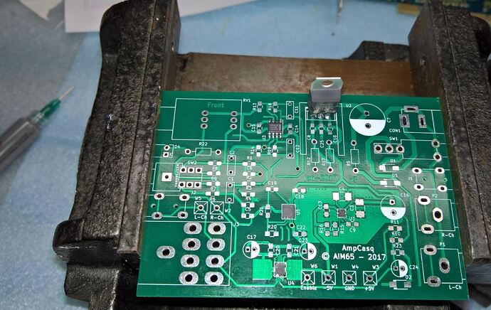
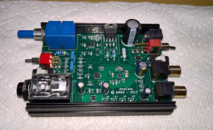
Heres in the pcb with the IC attached as well as a power reg . Notice the small IC upper left of the large tall standing part, this is a BIG 8 pin SOIC part thats smaller than the op amps you normally plug into a DIP socket…and then notice the other three smaller parts…they get very, very small especially the one in the middle right that is surrounded by a circle of pads…!!
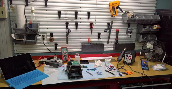
My workstation where I do some of my magic…
Getting there!
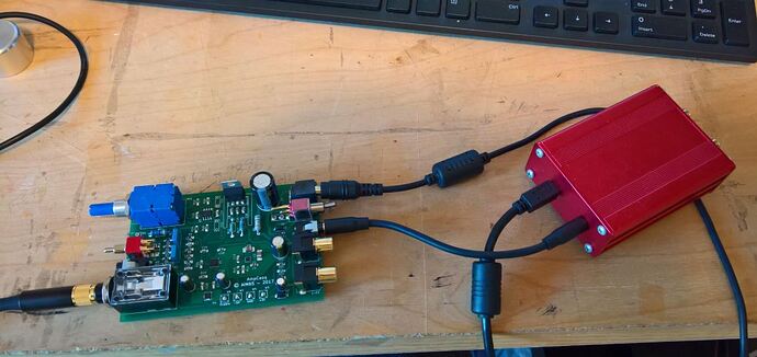
Testing…It works!!! Phew!! (Back when the ODAC was in favor)…
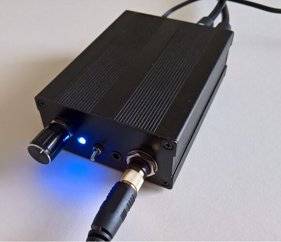
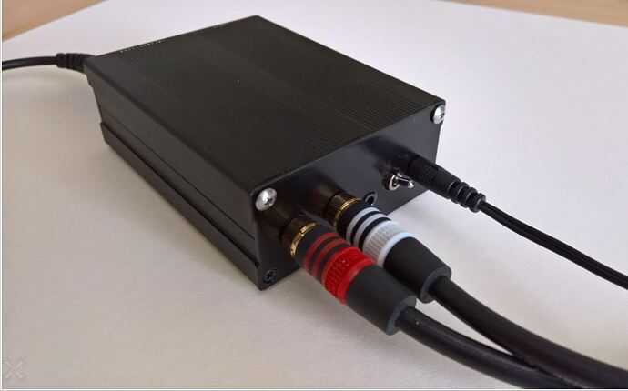
Finally all packaged up!
Ok for now, this was a lesson on how old farts can learn new things…after 40 years of soldering old school I can now lay down parts many time smaller and dense that I ever thought would be possible in the past!! From Vacuun tubes to advances solid state…
Take a look inside the THX AAA amps or the new Schitt Magnis and you will see these type ic’s being used in some of the latest headpone stuff and especially in phones and portable stuff…
How does it sound??
Thats next.
Alex
Link to DIY poject file: https://www.diyaudio.com/forums/headphone-systems/304684-ampcasq-opa1622-integrated-headamp-project.html
I still have a pcb if anyone is interested in trying this one!!! :>)
