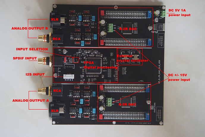
If you browse around sites like ebay or aliexpress you would run into various boards such as this R2R ladder dac board. This board in particular looks extremely interesting as it has an FPGA chip along with being 24 bit. Now I do know that there are like build logs for stuff like the soekris dacs but I never really seen anybody actually use one of these in particular. I wonder what a Bill of Materials would look like to get this thing working.
To tamper expectations: I am competent with Microcontrollers with only fundamental ideas about FPGAs. Still learning my ways with analogue circuitry (turns out it is harder than counting to 1 ![]() )
)
What that board does it take the problems of VHDL programming and integration hell from you.
I will go into what is missing to make it functional towards the end.
-
The black PCB potentially hides a lot of crimes. Lots of guesses going on below!

-
The NJM5534 Op-Amps are singles, so take care when replacing them! They are also not particularly great. They used the low-noise variety here.
-
No idea what the capacitor configuration next to the output Op-Amps is. Could be decoupling or frequency tuning

-
Input selection being a half-populated pin-header is weird, but just solder in another 2x1 in there if you intend to use I2S.
-
The individual R-2R FPGAs have their own local power input. Since that is what makes your sound, good filtering and regulation should be undertaken with the power you are sending there.
-
The 5V in at the top right is probably logic-supply. Probably not as crucial to supply clean power to.
The case is easy, wooden box would work, sheet metal and angle brackets is another option.
The final regulation before going to the board is also easy. Can just take reference implementations from the LM317/LM337 or LM78xx and LM79xx datasheets. Maybe throw some common mode chokes on both sides and filter caps (nF range) after the regulators with some bulk caps (uF range) before the regulators.
![]() You should not tinker with mains voltage when you do not know what you are doing.
You should not tinker with mains voltage when you do not know what you are doing. ![]()
The problem is getting the power to the point a linear regulator can work reasonably efficient. The problem is the ±15V at unknown current. No AC-DC supply I could find on a quick search offers 5, +24, -24. Two paths:
-
Either you get a transformer with dual 18V outputs, and run those through rectifiers with filtering and bulk caps. Has the advantage of being “easy” to do, you get all the problems of running a big transformer (or two).
-
AC-DC power brick/unit to do the initial conversion from mains to some double digit DC, dual rail (12V and 24V) would be fine, single rail 18V max. The lower voltage goes through the LM7805 (bolted to a beefy heatsink) for the logic.
Some DC-DC converter like the Traco 15-2425WIR putting out +24V and -24V followed by LM7815 and LM7915 (both on heatsinks) should do fine without generating tons of heat. Since you are running DC-DC converters, you need good filtering between the converter and the regulators (consult datasheets and best practices).
There aren’t individual FPGA’s, rather there is one FPGA (Cyclone IV) and two CPLD’s (Altera Max II’s), one for each channel. All you need to get this working is a toroidal transformer that has 2x12v and 1x9v (40 euro), a psu/filter board like the LT1764A (25 euro) from Audiophonics that outputs 15v and 5v (you can write them to make sure), an xmos or amanero input board, and a display, and a case. You can change the caps to some more reliable brands from DigiKey or Mouser, maybe change the RCA and XLR connectors to higher quality. The FPGA is likely there to provide clock management to the two external crystal oscillators, maybe also input management, custom logic for the ladders, DSP… You can change the opamps to opa1611s, there are dip8 configurations/mounting boards of this chip on audiophonics too, one of them in class A configuration (8 euro)… You can also change the two external crystal oscillators, but I cannot read the clock frequency, but the board can obviously accommodate larger rectangular through-hole models. You also need a power socket, on/off switch, LED indicator. Also consider mounting some heatsinks on the resistors in each ladder.
