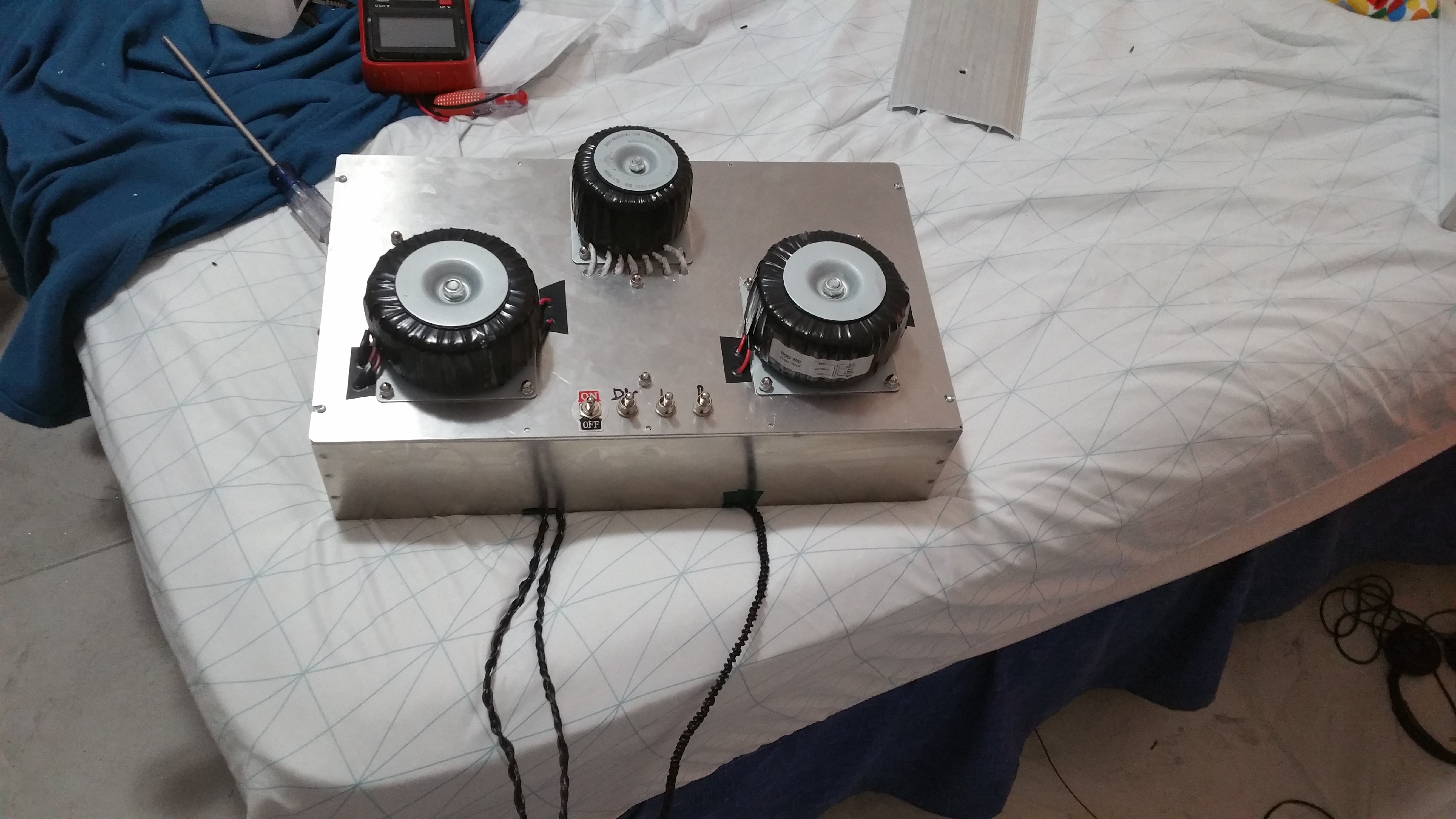
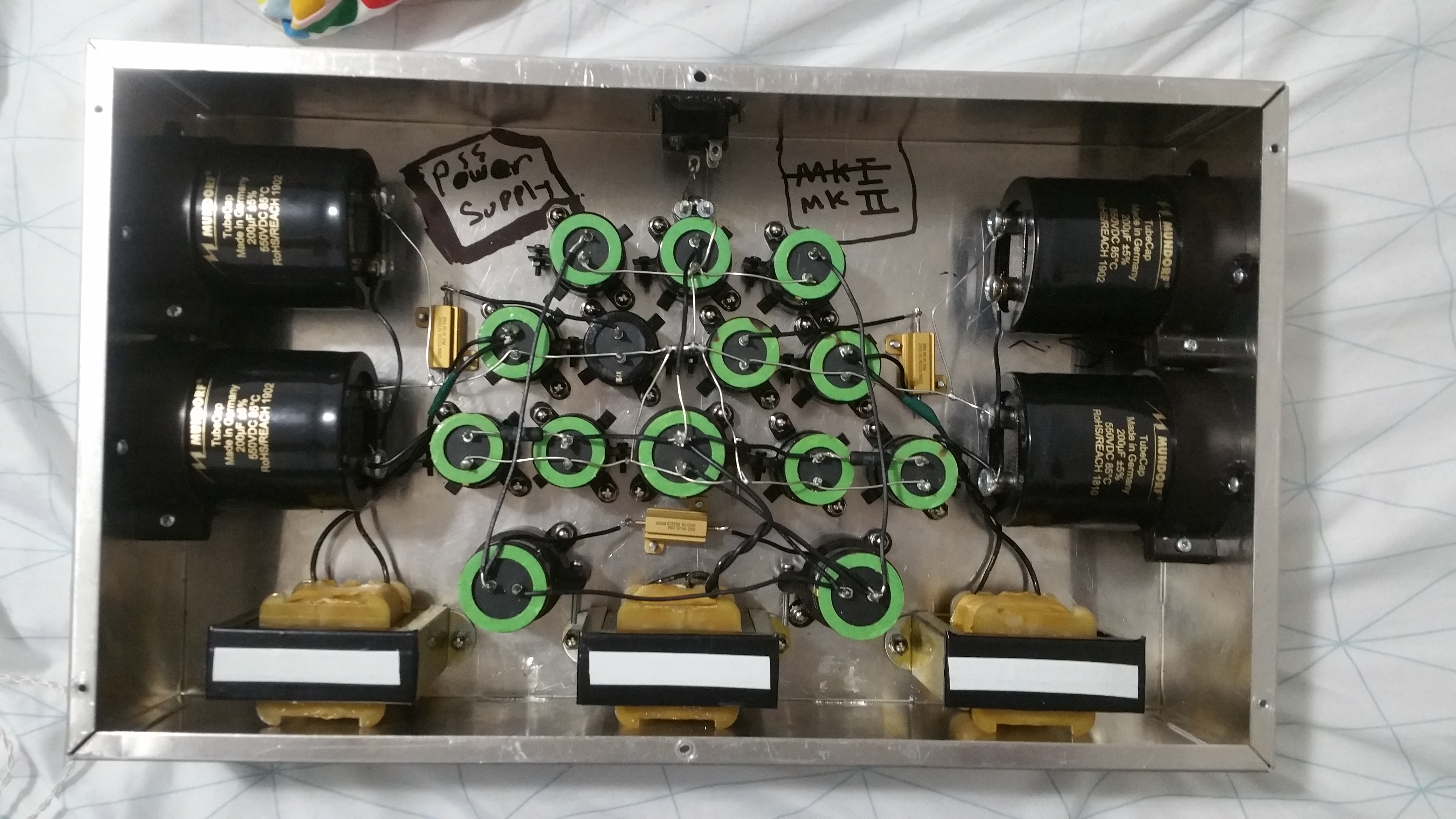
Oh also the power supply is 90% done, just need to add the Rectifier Diodes and attach the switches to them, as well as adding the wires carrying the plate voltage, which is 4 more, thinner though, made the heater wires (as seen in the pic) thicker and twisted as to reduce any resistance/noise the wires may carry since they have a longer distance to run. Same will be done with the high voltage wires, but those can be thinner since their heat isn’t as much of an issue with them in this case.
Just a few touches to finish it off but tomorrow it should be done. Afterwards it’s the amp portion which will be substantially easier to build (as well as 25 pounds lighter, the power supply weighs 30 pounds) will be finished during the weekend. Hardest part was honestly the power supply, the weight along and all the holes for the parts made it kinda hard to work with.
Oh also for anyone who is curious, I work on a desk doing all of this, and outside for holes (bad Idea to use a drill on top of your bed, and indoors too I guess, aluminum shavings suck), reason the amp is always on my bed is because it starts raining by the time I’m done and I always happen to be drilling a hole outside when it starts raining. Essentially the moment I feel a drop of water I haul ass into my room so nothing gets wet, afterwards I take a pic of it.
Idk kinda funny since I just noticed how weird it looks being on a bed instead of a desk, idk might take a pic of it on a desk tomorrow then, break the cycle.
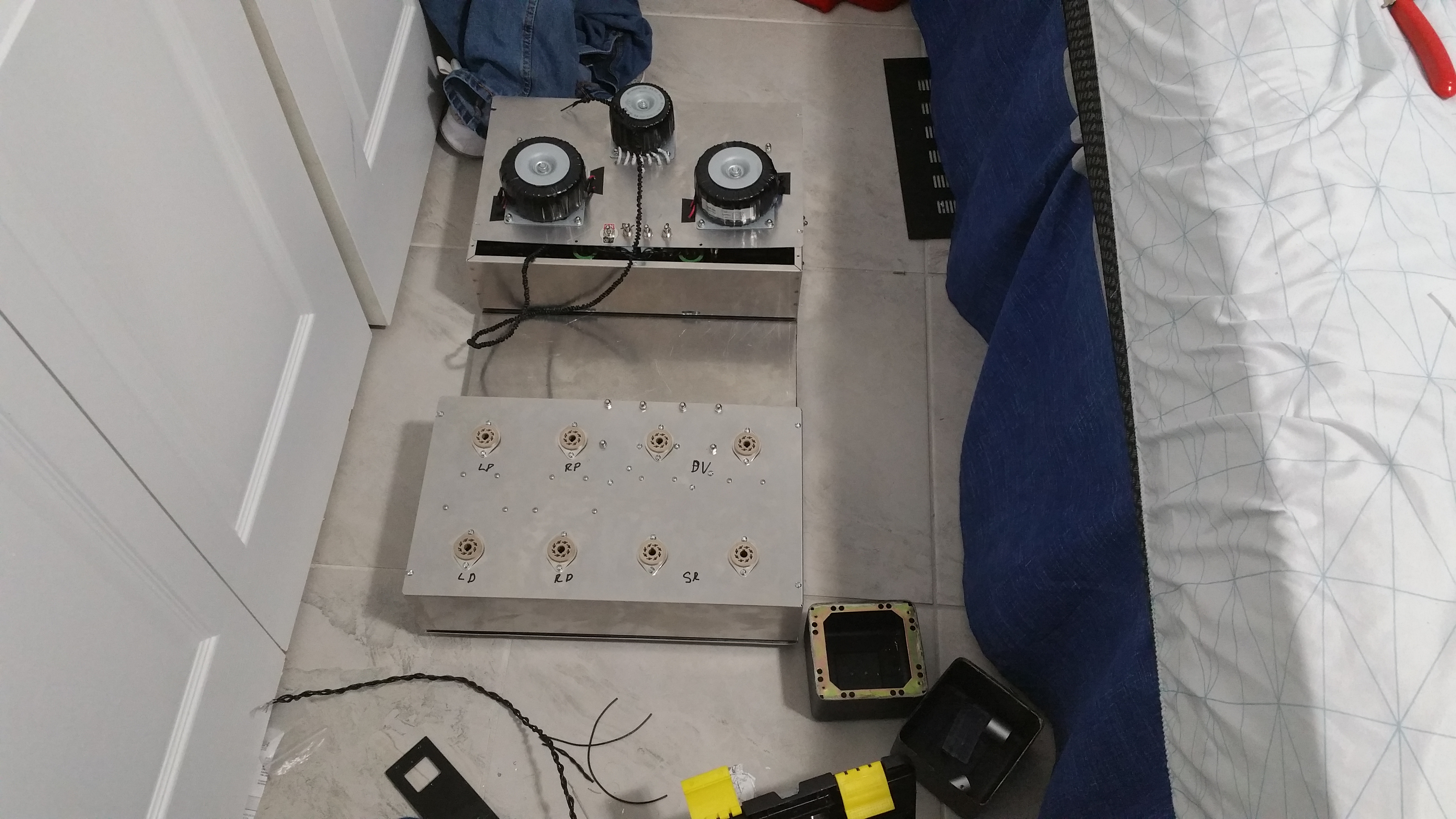
Ok, got an idea. So I couldn’t find plugs that could do what I needed them to (For a reasonable price), but then I thought, “What if I use Tube Sockets and Empty Octal Tube Bases To build Plugs and Sockets between the Power Supply and The Amp”?
I’m super sure that Tube Sockets and Pins can handle High DC Voltages and Heater Current (Since the tube can handle them when in a tube socket normally), so my question is, can this be done?
The only possibilities I can see of this failing is the tube sockets not being able to lock into place using a locking mechanism of sorts, which if the amp moves for any reason too hard it can essentially cause a short as well as resistances between the pins and the socket (Although that shouldn’t be an issue since the socket I’ll use locks tight as heck).
So the sockets/pins can handle this and not short then? I mean I have some spare sockets, all I need is to buy the empty tube pins. The Wire that’ll be used is 18 Gauge, Can handle 300V from it’s insulation, never gave me any issue from getting hot, even with high current AC heaters. Planning on using 2 in this case for 16 pins total, the amp is really heavy so it’s unlikely I’ll be moving it too much so almost sure the plug won’t move much.
Almost have the actual amp section done, just needs the Inputs/Outputs, Potentiometer and Switches, and the Power Supply just needs the rectifiers and it’ll be done too.
Essentially by tomorrow, the only thing that I’ll be waiting on are the parts to connect both together electrically.
(Also it’s like 3:50 A.M. atm, been working on it all day just to get the progress I needed so that I could finish the rest before Monday, after that it’s just getting the parts to connect everything together).
Oh I also bought the upgrades for Part II so that’ll be soon, and some fun tubes to test it out:
5998 Domino Plate Pairs
GEC 6AS7 Macaroni Pairs
Sylvania Chrome Dome & Bad Boy (Low Power Section/Pseudo DV Mode).
They all tested well, and the tubes allow me to test Low (GEC) vs High (5998 Domino) transconductance tubes on Planars, and I just like the look of Chrome Domes, and well, wanted to also see how a Bad Boy sounds, kinda curious honestly.
Nice to see you here after our discussions in Drop’s Darkvoice product thread. Awesome seeing you going forward with your amp project. Following in earnest
Yeah I was planning it out for a while, but I needed more information before going forward as well as study the parts I would use so I don’t mess anything up.
The parts are pretty expensive, SS, like the Beta 22, will have much cheaper components since alot of things are transistorized thus relies a bit less, albeit still an important factor to consider, on the quality of the components, so I kinda want to make it function without a hitch, as well as leave the space necessary for the upgrade down the line (Part 2 will be very soon).
It should function, I made sure to check everything three times over parts wise, and check the solder quality on all the boards in the amp, and use this discussion to get some ideas for the smaller things like interconnects between the power supply and amp and stuff.
Overall the hardest part of this amp was honestly the power supply. Lots of parts to consider, and the entire chassis had to be used, it’s essentially packed to the brim with stuff and is heavy, making it harder to work with when positioning it in positions to get my hands inside. Only for the building process, I made considerations so that changing bad/broken/outdated parts later would be easier than in most other amps due to the use of vertical clamps as well as taking advantage of the size of the chassis.
Comparatively the Amp portion only uses the lid of the Amp since the Actual “Amp” is small as well as very very light, since the socket, boards, and resistors/capacitors aren’t really that heavy, compared to the chokes and transformers of the power supply and the much larger resistors and capacitors.
Overall it’s been interesting, albeit has taken quite a while (Used up quite a bit of spring break to get everything done without overworking too much), but it’s fun, and I have to imagine, basing it on the design of other tube amps (DNA Stellaris, Zana Deux, The Studio, Mainline/Crackatwoa) that it at least has to sound better than the stock Darkvoice, maybe better than the La Figaro, idk until I plug it in and listen to it though. It will have quite a bit of power, especially using the 5998 I imagine.
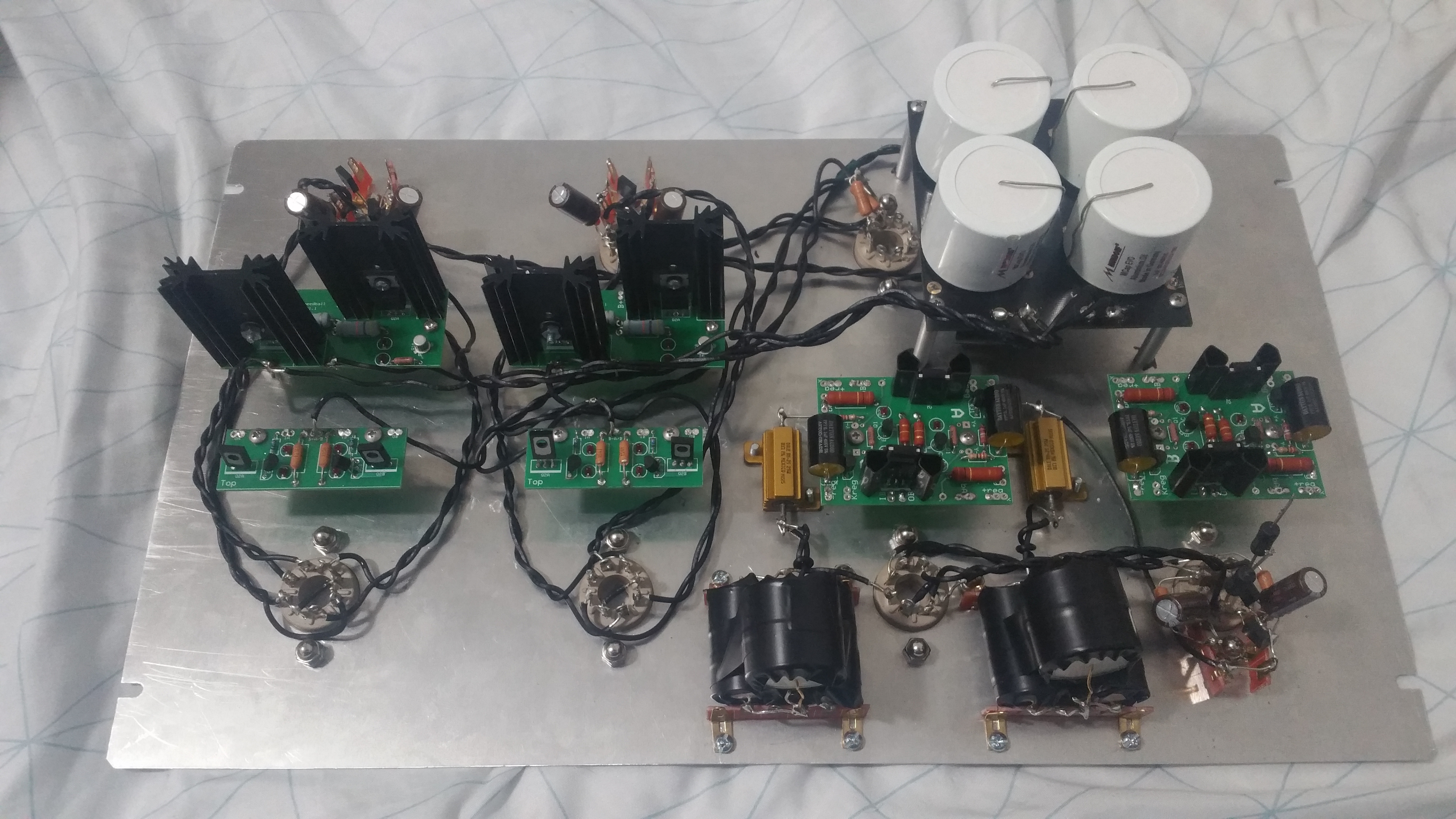
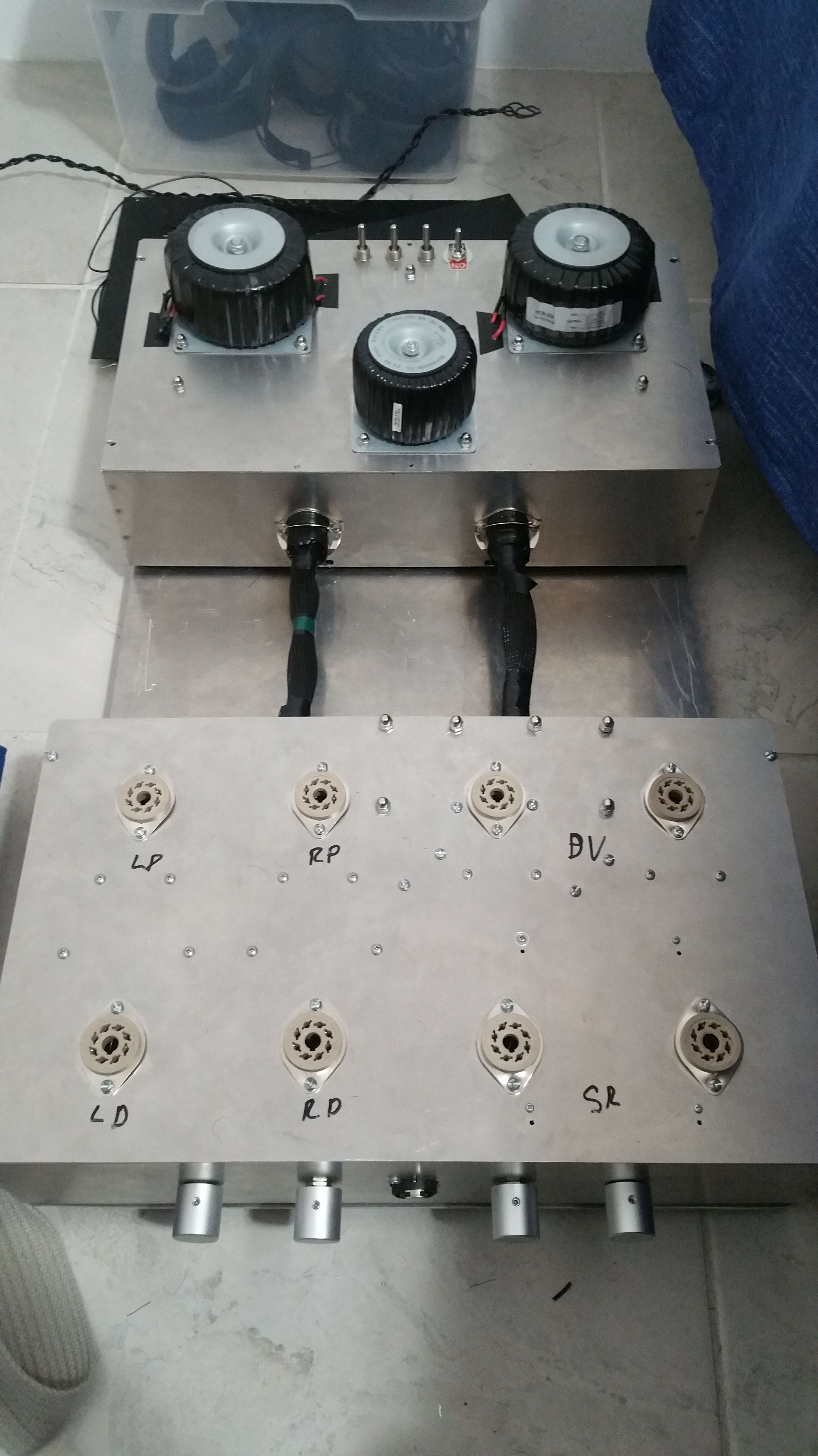
Ok so these are the current working pics of the Amp section, it’s technically “Done” but needs to have the connections to the power supply made first, which I’ll get the parts for tomorrow or Thursday, and work on it this weekend.
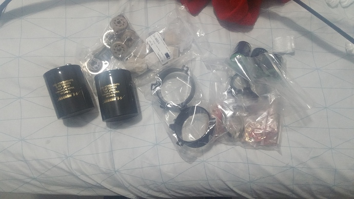
So I already posted this in the “What did you Buy Today” Discussion, but I finally got the parts to make the connections between the Power Supply and Amp AND the Parts I needed to upgrade the Power Supply to Mk II (Just some extra Capacitance where I needed it to be, as a bonus putting the caps in Parallel will also reduce the ESR of both film caps by half I guess, so that’s neat).
Honestly I was expecting it to take a few weeks, last time Parts Connexion didn’t have the film caps in stock so that took a while, guess I got lucky huh.
Top plate where the transformer is located contains the rectifiers as well as very simple limiter using resistors to reduce inrush current to plates, as well as switches to prevent high voltage to the plates until after the heaters have reached operating temperature. Forgot the video but I got the design for the limiter for a YouTube video, Carlson’s Lab I think?
Oh there was also a neat video from Carlson’s Lab about heater flash, where the heater flashes due to uneven resistances, but that tends to be mitigated in my case due to AC heaters heating a bit more evenly from what I read, besides the tubes I’m using aren’t known to have this issue, he stated it was more common in European Tubes than American Tubes, and I think it was more common in 9-pin tubes than Octal, don’t quote me on that last bit though.
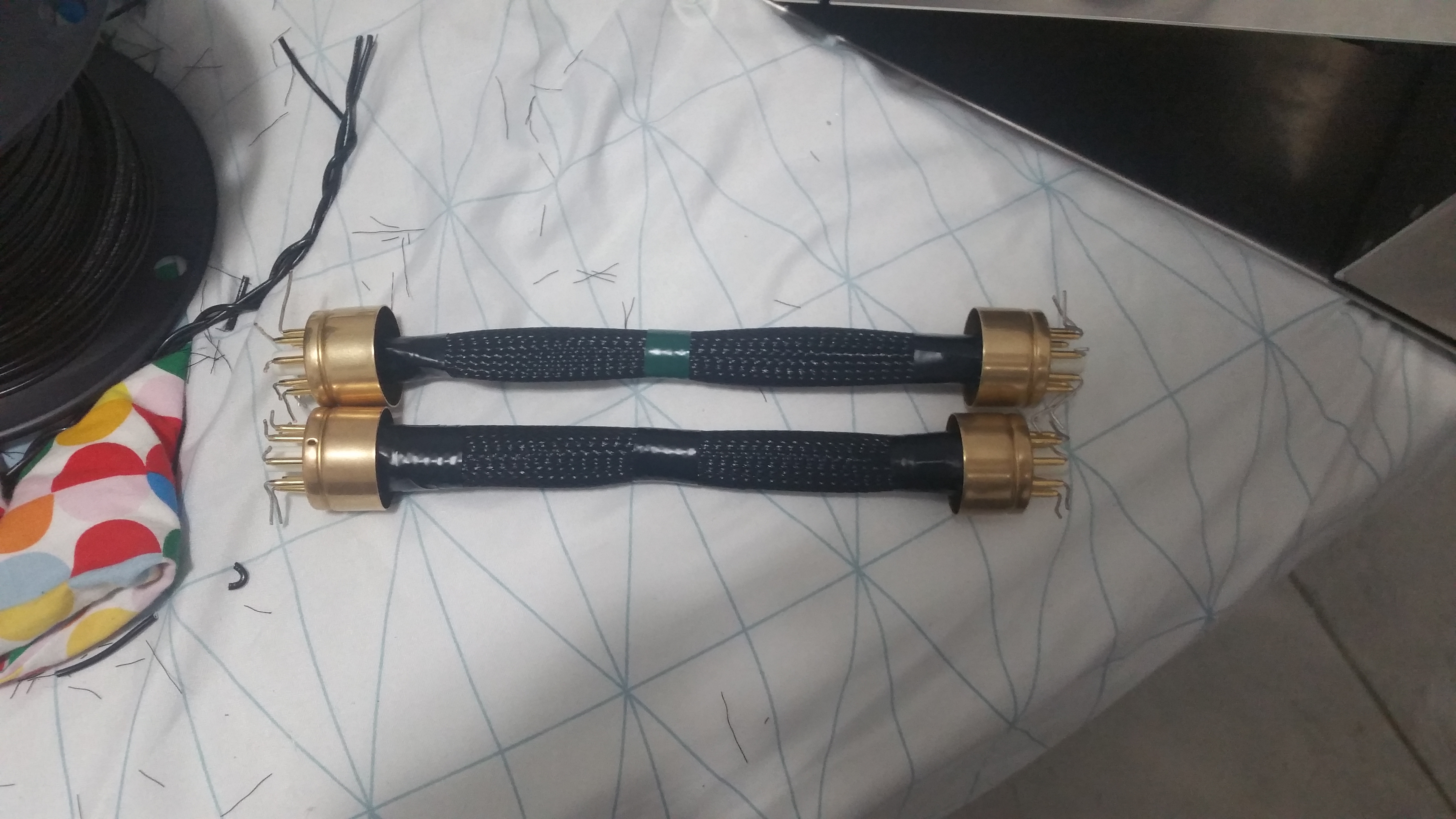
Just finished the interconnects, going to solder their tips and do potting on the casing so nothing moves there.
Also here are their configuration:
Black:
1: Ground (All) Left/Shield
2: Ground (All) Right/Shield
3: Plate Supply (All) Left
4: Plate Supply (All) Right
5+6: Heater (All) Left
7+8: Heater (All) Right
Green:
1: Ground/Shield
2: Power Tube Plate
3: Driver Plate Left
4: Driver Plate Right
5+6: Heater
7+8: Reserve/Unused
Also bought tube retainers for them that go where the socket is, tried them out, once the retainer holds them in place, you have to legitimately pull with quite a bit of force to pull it out, or even make it budge. Good since that means there is no way for them to move just from a bad fit.
Ok so quick update, decided to make a revision to the cables up top, made a MK II of them, made them fit better and prettier, but I need to buy 2 more Pin sets to make the other one. essentially they’re shorter and fit better than the originals, as well as make a tighter contact and just overall look better.
Amp is about 90% done atm, probably will finish it this next weekend since the power supply (Finally) is 100% done and the amp section is 80% done. Looks a bit “Made during a Zombie Apocalypse”-ish since it’s bare aluminum with thicc beefy interconnects connecting two boxes with a bunch of bolts to seal it together. Won’t win any contests for looking pretty or aesthetically pleasing but it’ll work well at least from what I tested.
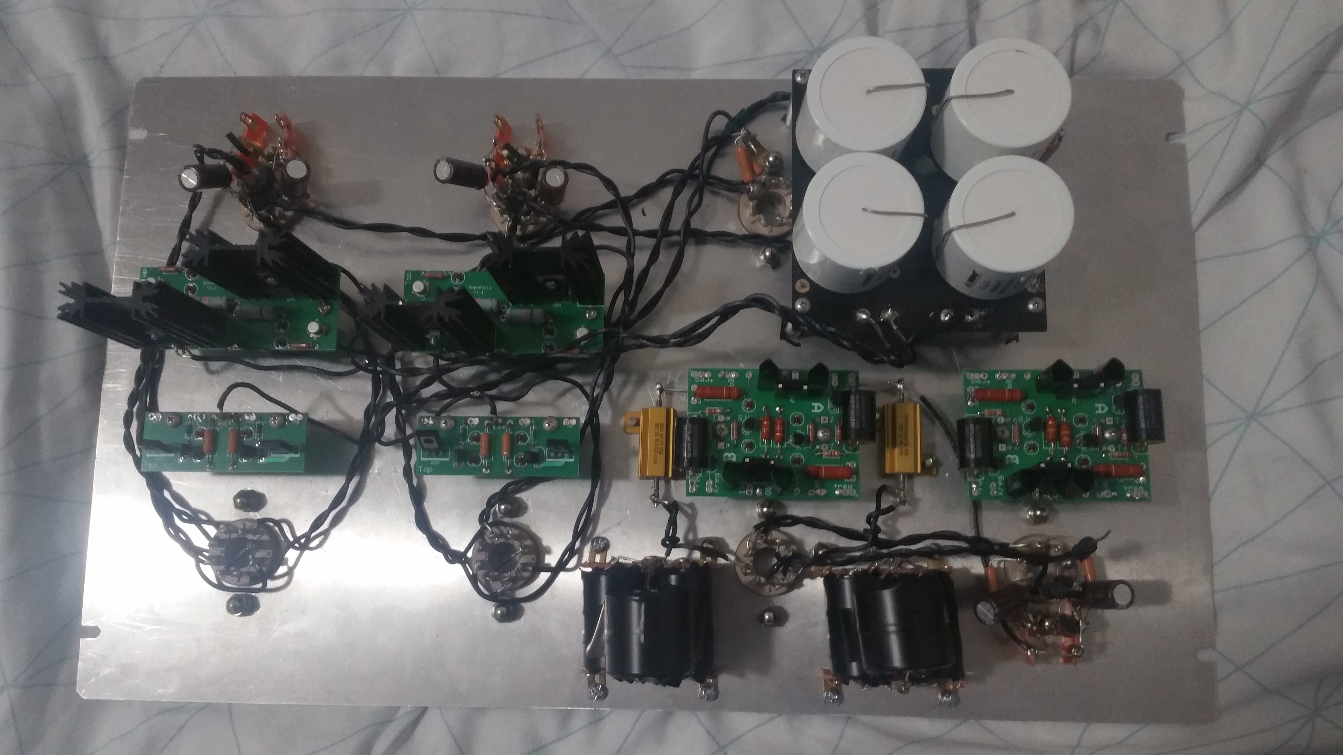
Ok so I’m 95% done, got a chance to work on it all day yesterday but I’m getting bombarded with tests/lab reports this week due to the Coronavirus shutting down my University, so everything is online and really really buggy. But this is more or less a pic of the amp almost completed.
Still don’t have a name for it though, and it still needs some touches like better feet to reduce vibrations and upgraded 4 50uF Mundorf Evo Aluminum Caps on the output (I was thinking 2 100 uF per channel but ESR may be lower using 2 50 uF each in parallel per channel).
Oh also, it’s BIG, but trust me the size was necessary, even now I’m working with limited space due to how much stuff is in it.
Just to clarify…you are doing this for fun, in your dorm room, and electronics isn’t even you major? You have learned everything from reading a book or 2, some help from a dude or 2, and trial and error. Am I close?
Ok, guess that’s the name then, honestly I can’t decide on one, and it fits, I’ll write in Sharpie on the front to make it Official.
I got an Aviation Repair Book from a friend, read it, and used the info there to take apart and Mod the Darkvoice to make it Quiet (pretty easy with a Transformer Swap Honestly).
Then I Modded my La Figaro to use 6J5 Triodes rather than 6SJ7 Pentodes since I like the Triode Sound more, had to tweak a few things since the Pentodes were a bit louder than the Triodes, although that was just feeding the Triodes a bit more Voltage/Current via reducing two resistors from 200 Ohm to 150 Ohm, but Keeping the 27,000 Ohm Resistors the Same. (Had to experiment with the resistances, used cheap resistors to see the effects of the resistance until I liked the volume scaling)
Afterwards I did the Speedball Mod and liked it with the La Figaro (Did the mod on the Darkvoice, didn’t like it as much, probably because of how the Driver functions in a Darkvoice v. Crack).
After That I went and Got a Shunt Regulator Board, changed the La Figaro transformers to handle 6SN7s, and like how that Sounded more (Half the Tube for Audio, Other Half for the Regulator).
After that I started to wonder if an OTL can handle inefficient Planars with the right set up/power, so this is where this design came in, it’s essentially the modded La Figaro, but uses dedicated 6SN7s for the Regulator, and Dedicated 6SN7s for the Audio (More Power presumably using 2 triodes instead of 1, besides, this way, if I ever want to mod it to use it as a Push-Pull, I have the necessary Triode Count to do so).
Transformers were scaled up to use 6528s for Even Lower Output Impedance If I felt like it (Using 5998s though since I head those sound better, and atm I only own Dynamic Driver High Impedance Headphones), the Power Supply Voltage was increased to compensate for the drop in the Regulators, and the Signal Passes though what is essentially a lower noise version of the Darkvoice Circuit (I REALLY enjoyed the Flavoring of the Speedball La Figaro with a Quiet Modded Darkvoice Preamp).
This essentially has more power than the Speedball La Figaro with the Quiet Modded Darkvoice Preamp, can use more tubes since the Max current it can handle is 7 Amps for Heating per Transformer, so it can Handle 2 CV181s and a 6528 Per Channel at the Same time, Has much higher quality Parts (I could fit Mundorf TubeCaps inside of this amp because it’s MASSIVE, although I was cutting it close space wise).
The only thing idk is if it’ll sound good when I first power it on without some tweaking, but I can only imagine based on the Prototype that it’ll sound as good, or better with the extra precautions I’ve taken towards reducing noise.
Shielding is 1mm thick for any cable carrying an Audio Signal in the Amp, and 2mm thick for the interconnects between the Power Supply and Amp, the Heaters also have 1mm thick Shielding, and everything is in twisted pairs, Heaters are also “Center-Tapped” using resistors to Ground since I’ve read that tends to make them Hum much less (This can be seen in the Crackatwoa), Heater Voltages are between 6.24 and 6.29 Volts with the Tubes plugged in so everything is being heated adequately, or at least there isn’t excessive voltage, All resistors in the Amp have a tolerance of 0.1% or less, with the Grid-Stoppers having a tolerance of 0.01% Z-Foil, all Grounding Points have less than 0.01 Ohm of resistance to it, and all Grounding Points are soldered directly in some way or form to the Ground Pin in the inlet to assure a direct connection to Ground and not just through the Chassis.
Idk, if I hear any noise I’ll suss it out eventually, honestly I’m in Pre-Med atm, finishing my Freshman year to eventually get a Masters in Developmental Psychology, maybe a Doctorate when I get older and have a bit more time/money/experience, so electronics isn’t really my forte, I kinda got bored one day and did naughty Mod Things to my Darkvoice, and here we are now.
I mean the book initially helped, getting questions answered here and on the Bottlehead Forums helped immensely, but it’s mostly trial and Error as you said, quite a few shocks and burns on the way though (Once got a 250 VDC shock from the 820 uF caps in the DV and that hurt like hell, I know because I drained the Cap when I touched it).