Tube Amp (Working Title: Darkvoice 336SE MkII (Part 1/3)

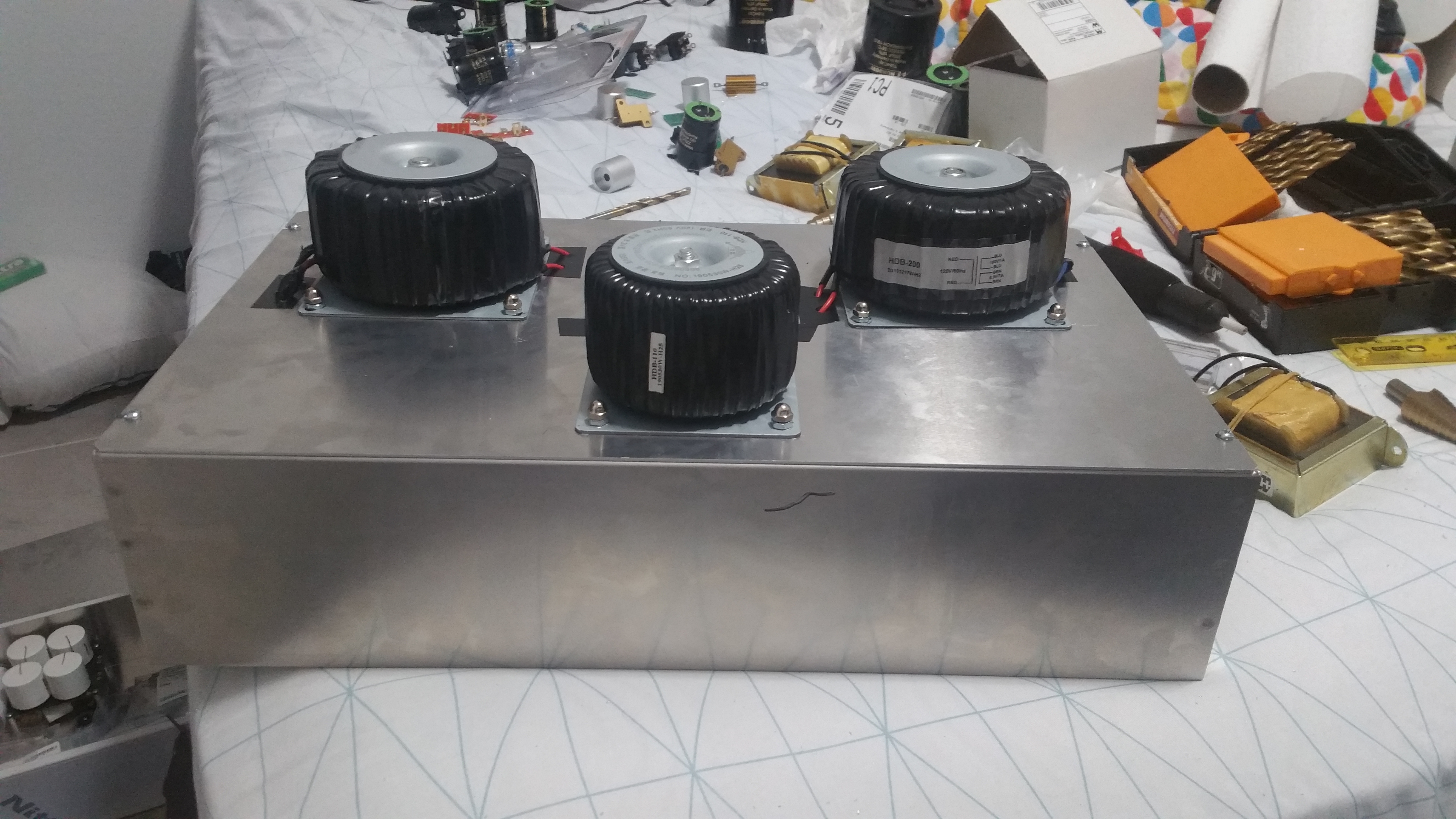
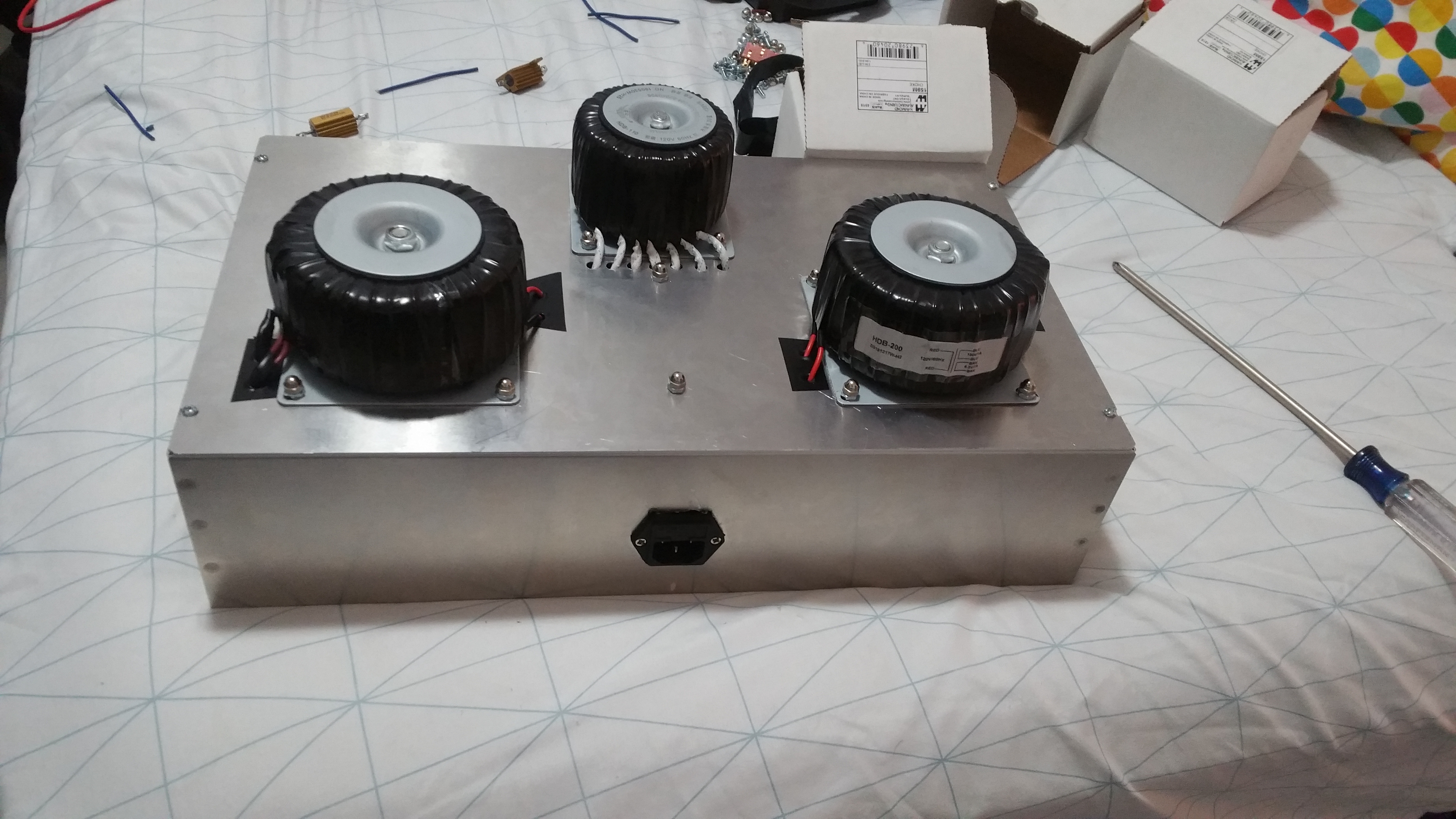
Ok, so, gonna start making that amp I was planning for a while, essentially, it’s supposed to replace my Darkvoice 336SE, hopefully it sounds a bit better than the 336SE, idk. So here are some pics of the Power Supply Box (More Stuff Inside) With a possible layout of all the parts:

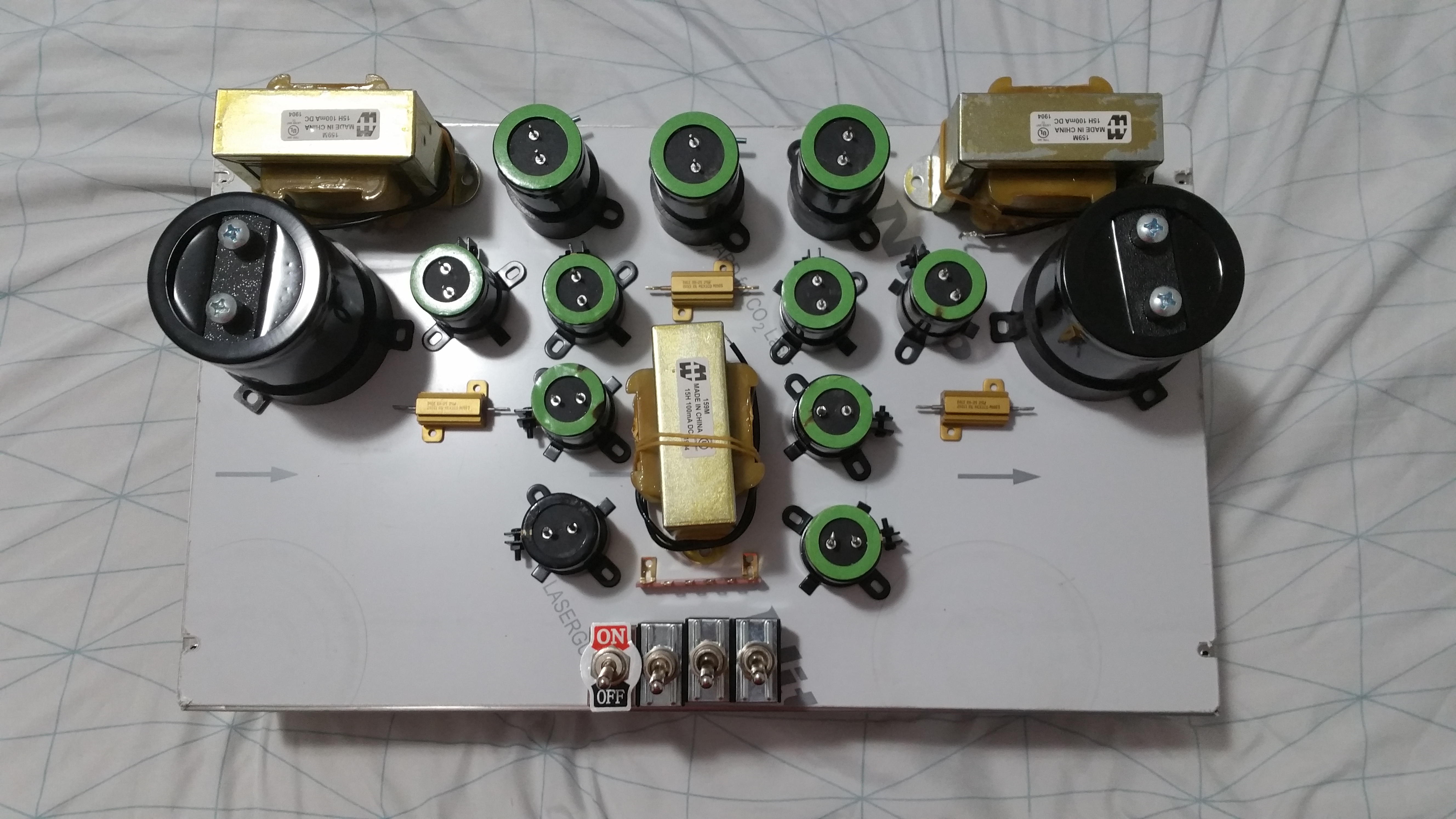
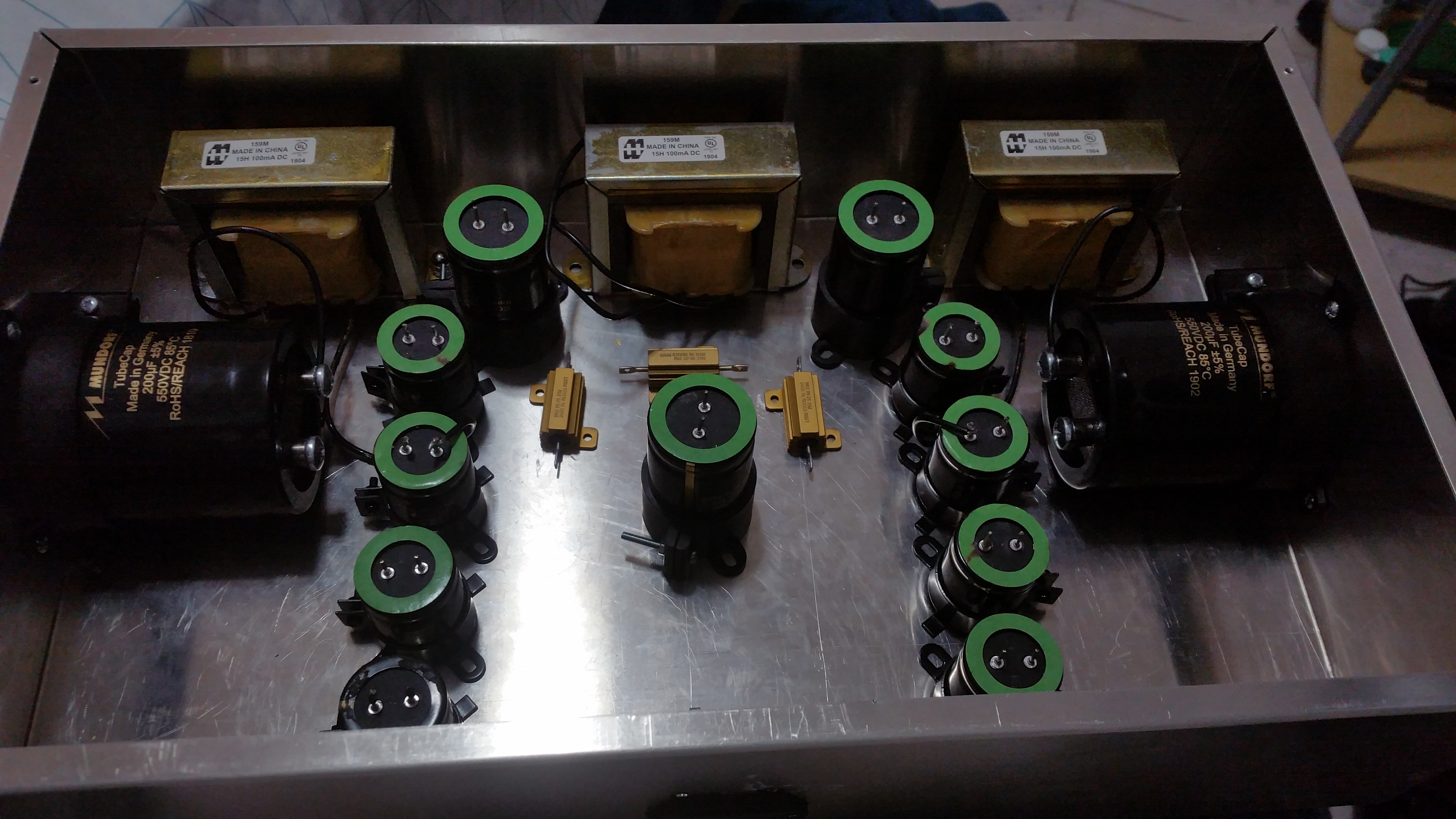
The Blackened bits was me just getting bored as well as testing certain things, doesn’t affect performance, all parts work perfectly and have no deformations on them, they all have their retained tolerances, and again, work as they should, also, leaving space for some extra capacitors in the Part 2 of this amp.

Again, it’s not what’s on the outside, but what’s on the inside that counts (Albeit the capacitors will be on the outside kinda since I need space for the Transformers/Diodes/Extra Capacitors for Part 2 on the Inside, not their contacts though . . . well when I’m able to open the necessary holes you’ll see what I mean).

Also this box is a separate power supply, the amp bits will be in another identically sized box, just wanted a separate power supply since the chokes and the transformers can put some noise into the actual amp if they’re too close, besides, makes it seem all fancy like having two boxes (Srsly tho, with the size of the capacitors and the other stuff inside the box like the transformers, I NEEDED a separate box for everything to fit.

Also the Chokes will be kept on the outside, with the transformers on the inside, doesn’t matter since the choke’s frames shouldn’t be capable of shocking me, besides It’s unlikely I’ll be touching them while the amp is on, and I’ll probably get a small cover for them eventually, just wanted them to be far away enough from the transformer, while also not being too close to the Amp portion.

Also the chokes don’t seem to pick up any form of external interference, so I guess I just have to keep them away from the transformers and they shouldn’t pick up any noise, I tested their positioning similar to how chokes were tested for the Crack in this post: https://forum.bottlehead.com/index.php?topic=9414.0.

The 4 Switches in the pic are there to essentially act as a soft start of sorts, let the tubes heat up first on the amp side, then I can apply the high voltage once they seem to be hot and ready, make sure they last a bit longer, other than that, switches are cool.

The On/Off Switch (Goofy looking but I like it), turns on the heaters, the other three switches apply the High Voltage to the different parts of the amp when the tubes are ready.

Oh also for fun, here’s a pic of my Darkvoice on the inside (Is it crude, yes, very much, honestly it’s kinda embarrassing, like my amp is getting their nudes shown, does it work beautifully however, oh yes, yes it does.):

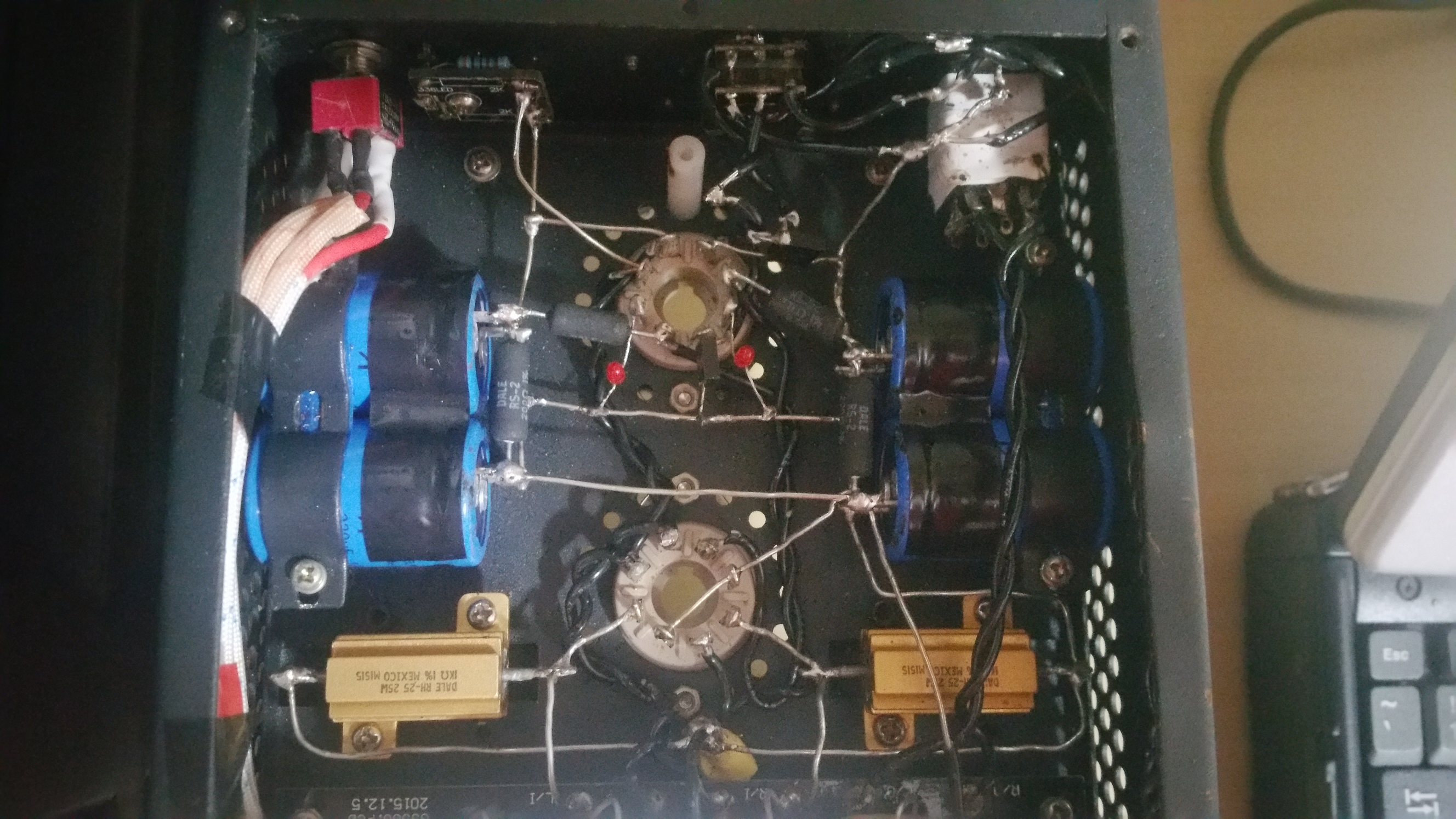
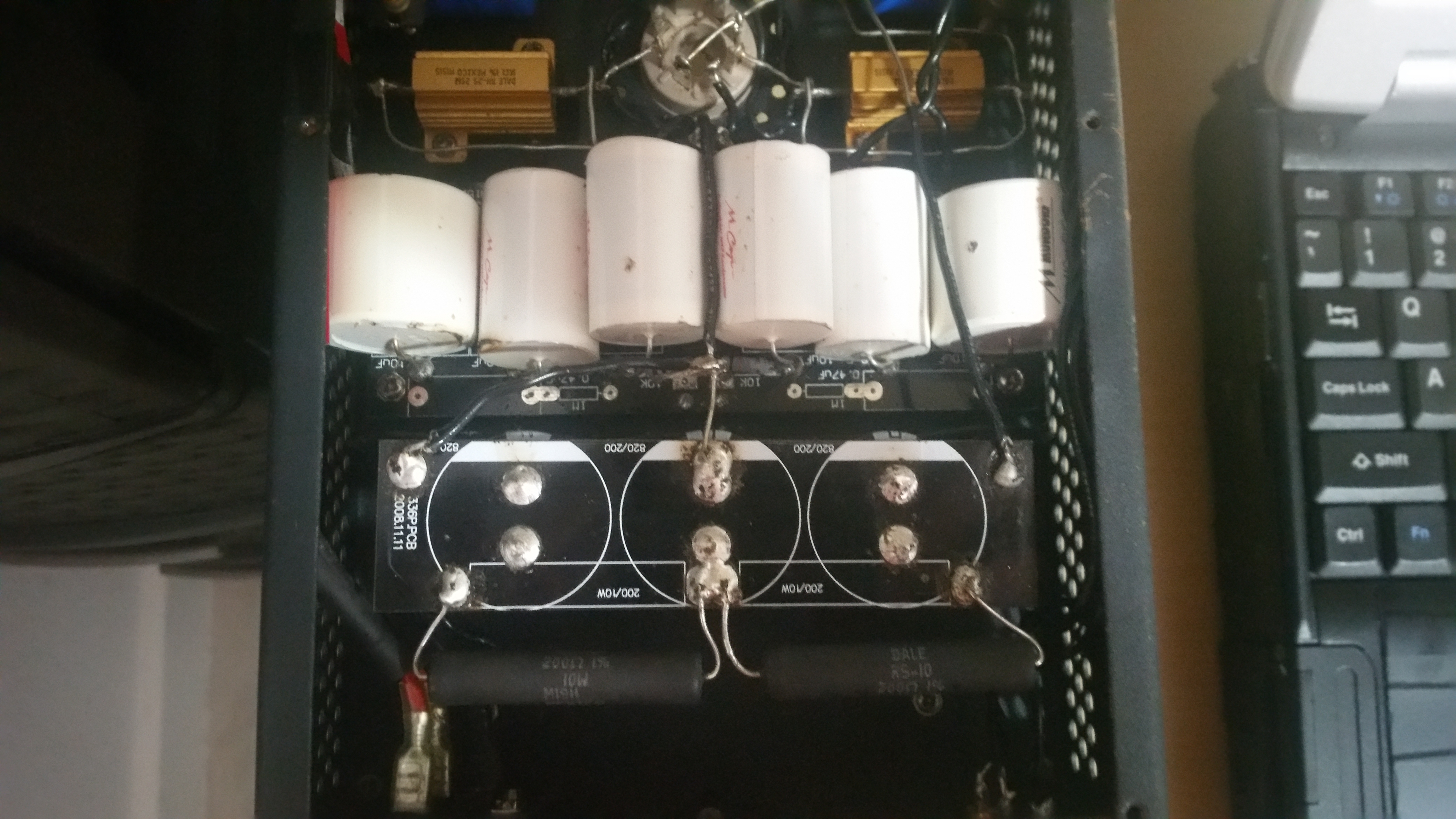
Yeah the tiny enclosure was a pain in the ass to work with, especially since I had to work inside the case (Also it was the first time I ever tried to solder something, soooo, yeah, if you would have seen the first and second attempts you’d wonder how I didn’t burn the house down).

Essentially I’ll be taking a page from Bottlehead’s book and making the actual surface where the circuit is just a single plate, that can be easily removed and easily moved around, without case walls blocking my hands or my iron, makes it easier to work inside, makes it easier to later modify.

It was raining this entire weekend so I couldn’t get started in making the holes in the enclosure or in the plate where the actual circuit is going (wanted to do it outside so I wouldn’t get aluminum shavings in my room from all the drilling) so idk, the pics here are just placement ideas.

I have spring break next week and it shouldn’t rain during that time, so I have all of that time to actually finish it. I have nothing important school wise this week and I aced all of my exams which is also great, gives me more time to plan out positioning and other stuff, other than that, this post is kinda just to open the thread and later just show off what I’m doing, it’s a pretty simple design but everything is beefy, and won’t break easily, besides the parts are pretty good quality, so it shouldn’t be too bad for what I’m planning.

Oh also that white peg in the Darkvoice pic is a remnant when I tested Speedball on it, idk didn’t pan out as I wanted it to, but oh well, it was a learning experience.

13 Likes

Oh, Yeah…Imma so interested to see how this comes out. Good luck!

IMG_1953

3 Likes

Thanks, been planning it for a long time, ironically the thing that has taken the longest was getting the chassis, took 3 weeks for them to be made and delivered, and after that I still have to make the holes in the chassis which thankfully I have a week to do since spring break is next week.

I mean, the hardest part now are the holes, afterwards I could probably finish the amp in about 5-6 hours if I did it straight, true I’ll take breaks to be able to think on how it’s being built, so I can catch any errors I make, it’s not a great idea to rush things like this, especially with the cost of the components at hand.

Either way the prototype was really really powerful, albeit noisy and unfocused since the 6J5s I was using were old, as well as not taking nearly the same amount of precautions on noise.

Using Chokes, Using Grid-stoppers, Virtual Ground on the Heaters, Better Grounding Points (although that wasn’t really an issue in the prototype since there wasn’t any ground loop issues).

True this version will be using 6SN7s instead of 6J5s, as well as having a shunt regulator, and C4S. Essentially I bought Speedball Kits and Stereomour Shunt Reg Kits to test this out.

Some of the Values have been/will be modified to further optimize the boards, and their implementation seems to really take the simple design of the DV to a very very very different level (Idk if you want something more analogous, look at the Crackatwoa, but more power and a beefier power supply, with an even lower output impedance and a further range for updates/mods, also kinda like the Zana Deux in that regard), especially having dedicated power supplies so nothing works too hard/better separation.

The best part of this amp however, is the modularity, the Power Supply is so overcompensated and the way it’ll be built, it allows for the removal of the Amp plate circuit, and it can be changed out to use different topologies, different tubes (In the 6.3V range, although that may change with the MKIII Transformers, maybe allowing for 2A3 and 300B tubes, but that will be quite a long time, maybe I’ll never do it, idk,depends on how much I like the sound of this amp, I want to enjoy this design first, MKII will be soon though, adding more capacitance to certain parts of the power supply).

Also to explain the MKII and MKIII:

Right now I am making MKI, the basis of the amp, powerful, Low Impedance OTL, but can be upgraded when necessary in case the OTL aspect fails and Output Transformers must be implemented for lower impedance headphones.

The Low Impedance OTL concept came from looking at the Zana Deux and it’s use of 6C33C tubes, issue is, I’ll be kinda limited in tube rolling options if I went that rout, so I decided to use a 6528 tube as the basis for the low impedance Output, since it’ll also allow the use of 6080s, 6AS7s, 5998s, etc.

MKII will simply increase power supply capacitance as necessary, since I didn’t have the initial funds to truly make the best power supply for this particular amp, I mean, MKI works fine, but it can be better, essentially I’ll buy two more 200uF Mundorf Tube Caps, and 10 150uF Mundorf Electrolytic Caps, just increase things as necessary. Issue atm is that the power supply Film Caps are in line with the audio circuit in this case, but their capacitance is a bit low relative to the preceding caps, so MKII is essentially just to revise that.

MKIII will have the transformers changed out to even Beefier Transformers, essentially the BEEF transformers can each output 10 Amps of Heater Current if necessary, so nothing will be out of bounds for any part of this amp, again, I have to take steps to accommodate this space, but from what I can see, it is certainly possible.

Oh as an added bonus, the amp allows me though the use of two knobs (pain in the butt to figure out the correct combination to allow this, since these knobs act as switches essentially for other things, such as preamp outputs, headphone output, etc), to use the amp purely as a Darkvoice circuit, well a Darkvoice with German parts and Chokes, but a Darkvoice nevertheless. Idk, thought that was funny, lets me have 2 amps in one, so an AmpAmp.

Also I feel like it’d be funny to call this amp the Darkvoice Mini, just for shits and giggles, idk, it does weight 50 pounds though so idk how to make it portable, maybe put wheels on it and tie a string to it like a wagon.

2 Likes

Ok so it was still raining until evening which sucked, but I was able to atleast drill the holes necessary mount the transformers, idk, I’ll post more tomorrow when I finish the power supply.

Oh also if anyone here knows where to get 14 Pin Umbilical Plugs and Sockets, it’d be much appreciated. That OR (since I couldn’t get a definitive answer from the spec sheets I read), can 3 Pin XLR Plugs/Sockets handle 7 Amps @ 6.3V AND 1 Amp @ 150V, idk seems easier to buy XLR Plugs and Jacks and just make beefy wiring for them to act as Pseudo Umbilical Cables. Like idk if the pins of the XLRs can handle that much current, idk tho. I could order some tomorrow and have them here by Thursday, they only need to be about 6 Inches per cable at most, just to separate the Power Supply and the Amp enough so they don’t interfere with each other.

4 Likes

XLR is not meant for high voltage.

Neutrik NC3FXX spec:

For high voltage, you want as much seperation between traces and contacts as possible. For your 150V supply, look at PowerCon style connectors.

2 Likes

You could use aviation style connectors they’re rated for enough voltage and current, and aren’t going to come apart accidentally.
I use them a lot in projects.

2 Likes

Yeah I saw Neutrik powerCONs on Mouser but their spec sheet never specified if they could work for DC, A bad connection and a DC spark won’t get put out as easily as AC, also I wrote the wrong number on the last post, I meant 190VDC @ .1A (I wrote the Transformer’s Spec instead) as the total Plate consumption for the tubes, idk, gonna check the Neutrik Site to see, thanks for the link btw.

Yeah I was looking at MIL spec connectors but they seem pretty expensive, especially for the amount of connections the power supply needs to make with the amp, idk, if you could recommend a site to buy some aviation connectors that’d be appreciated. Also thanks for the reply.

Molex Brad Mirco-Change M12 is rated up to 250V AC/DC @4A


Will give you an industrial rugged look.

1 Like

I bought a ton of them of ebay at some point.

1 Like

This is the awesomest thread. I don’t know much at all about electronics, but I still look forward to every post!!

3 Likes

Ok so I was thinking about how I was going to link the Power Supply and the Amp Portion, and while wire seems cool, I think I have a more comical solution.

So I was looking at the Torpedo MKIII, and seeing it’s length, I decided to match it with girth, and thus, my amp will simply be two chassis Placed on a long and sturdy piece of sheet metal, allowing ~6 Inches of Separation between both with the wires being, well, you’ll see. It was a sheet meant to be capable of holding quite a bit of weight, It can hold 200 lbs At least from testing.

Essentially the connections will be direct, soldered from one point to the other, but the wires will be hidden as to ensure safety from well, possible exposed wire electrocution.

Oh Also here are some pics of the power supply so far on the outside and A bit of how the internal layout will look, leaving space for the capacitor upgrades that will happen in a week or two from now, I got my Phonitor Refund, might also start work on a Beta 22 when I’m done with this amp, although that one will be significantly smaller and easier to work with voltage wise.

I’m still considering a few factors but this way the resistors are far away enough from the capacitors so heat won’t be an issue, as well as the inductors being close to the chassis so they can radiate their heat a bit (I will add some ventilation holes later to make sure there is some airflow for the Power Supply)

Also the diodes are still missing since I’m still wondering how to place them, but more or less give me another day and the power supply will be done.

Oh also, may use some silicone to prevent the transformers from vibrating too much if that’s an issue (It worked with the prototype, so might help here).

Oh also, kinda wondering about names for the amp, I mean, Darkvoice 336SE MkII is a bit of a mouthful, so idk, maybe:

Girth Torpedo (Girthpedo?)
50 Pound Sound
The Amp That Came From The Black Lagoon
Don’t-I-Y
D-I-Yoinks
D-Oof-Y
D’oh-I-Y
D-I-Y-inator
Hi-F**ked
The German Soundorgy
The Desk Snapper
The Table Breaker
Some Assembly May Be Required (To Break Some Cans)
Poor Man’s Hi-Fi
Rock And No
Tubetrip
Space Heater (Now With Stereophonic Audio)
Really Starving Student
Raw Power
Can Baker
Mr.Tube (Mrs.Tube?)
Stereophonic Tube Audio Nexus (S.T.A.N)
Sweet Warm Tubelabama
Back In My Day . . . The Counterargument
VALVe Amp (Not on Steam)
Cat Warmer
Sounds So Heavy
Solid State’s Older Brother
Socket Singer
Solid State Killed The Tube Star
Steampunk Wetdream
Shocking When Wet
Tubieonetwelve
Stairway to Tube Heaven
War Tubes
Warm Side of the Tube
Tube Diver
Happiness is a Warm Valve
T-t-tubes and The Valves
Sparking Tube Flash
House of The Warming Tubes
Heart of the Soundrise
21st Century Tube Amp
Tube-Rex
Pretty Young Tube (P.Y.T)
Tube! Tube! Tube!
Sweet Valve O’ Mine
Tube Binge
Tube, Wolfram City
Komm süßes Ventil
The Amp That Tubed The World
Straight to (Tube) Hell
Neutral Grid Hotel
Tube Loaf
Tubed Underground

(Idk I’ll Add more Names (puns) when I can think of more).

5 Likes

Love seeing your work keep it up

1 Like

Hey so just out of curiosity, I heard Rhodium is relatively long lasting and won’t scratch as much as Gold, so kinda tempted to remove the plugs of my cans and add some Rhodium plated plugs to them.

I don’t care about if it’ll “Make my System Sound Better” as I’ve read, I don’t really buy into that too much but to be fair, Rhodium is more resisitve and may affect how the amp reacts to the load since ik they’re more resistive than Gold, but out of curiosity, would it be worth it to use Rhodium as to prevent scratching the plugs when inserting it into my amp.

Oh and as a side note, I ran out of screws, bought 50 but I guess that isn’t enough, gonna go out later today to buy ~100 more, I really want to finish the power supply (Hardest Part) before Friday at least, the actual amp part is much easier to work with honestly, less things to worry about and heat isn’t an issue in this case since the hottest thing in there are the Cathode Resistors and Current Sinks, which have plenty of space to ventilate and very large heat sinks to work with.

I think you’re over thinking it, you should get 10,000’s of insertions from a gold plated plug.

If you’re going to buy into the audiophile thing you should use Copper plugs and copper connectors (assuming you used copper wire internally to avoid any dielectric effects at the junctions between dissimilar metals.

I certainly wouldn’t bother with it, but that’s just me.

1 Like

Thanks, just wanted to see how much more a Rhodium Plug would last vs Gold Plated, honestly though the Jack being used on the amp is a high quality Neutrik so it’s unlikely scratching will be a major issue either way. Guess I’ll just keep the ones they have now.

Also the internals are tinned copper wiring but other than that the inlet is the same one on the Darkvoice since it works as intended (pretty hard to mess up an inlet honestly), and the tube sockets are Belton Sockets since from experience they grip the tube really tight and don’t break the bank like more expensive sockets (Seen some on Parts Connexion ranging to 20 + bucks each).

PS can you build me a Pass Audio amp on the cheap?

2 Likes

Well I was thinking of a Beta 22 but this also seems doable.

If I had a schematic of the amp (Or maybe some very very high res pics of the board, although it’ll be a pain to figure out the transformer values without a schematic or a details about it’s secondaries and their VA values) I could most likely build it, especially if I could find a business that can manufacture PCBs for me. Honestly surprises me how minimalist the HPA-1 is, I like it though from it’s looks, less parts for a great sound, kinda contrasts the Phonitor since that thing was just packed with parts and boards.

Idk, I’ll probably stick to building a Beta 22 though, still deciding on a 3 or 4 board design, both have quite a bit of power, both have a similar concept of sinking or sourcing the current leaving the transducer as to not send it to ground and instead throw it back into the headphone, except one does it using balanced and uses two Sigma 22 Power Supply Boards, and the other is Unbalanced with only one Sigma 22 Power Supply Board and does this using a third “Active Ground” Board (Essentially a Beta 22 Board for Ground, took me a bit to wrap my head around it, but it’s cool either way).

From what I’ve read (https://www.head-fi.org/threads/amps-that-can-drive-the-hifiman-he-6-planar-headphones.529873/) the three board configuration can push the HE-6 without issues, idk how reliable the source info is, but great news if it’s true. I don’t mind it not being balanced if I do go with a 3 Board design, saves me the trouble of having to switch out to balanced connectors often if I switch between this tube amp and the Beta 22, as long as it sounds great, but idk if there is any meaningful difference between a 3 and 4 Board design.

Well there is a 5 board design that can be both balanced and unbalanced using switches to use either Active Ground unbalanced or 4 Board Balanced, which seems like the best of both worlds, but idk, need to figure that out if I do go that route.

Oh Also, Here be a Pic of an HPA-1:

Theres a thread on DIYAudio.com with a guy who built a copy of an HPA-1 that includes a schematic and i think a PCB layout. The designer of the HPA-1 even chimed in and said it was very close.

1 Like

Huh, might be curious to build, but I’ll still probably build the Beta 22 first, since I can buy the PCBs already printed and probably knock it out in a week when I get all the parts (Mouser tends to be pretty reliable in getting me what I need in a day or two).

Seems easier to fit in a big chassis, or use 2 separate chassis, albeit with a much lower voltage than a tube amp, so I’ll have a wide range of hirose connections available to work with.