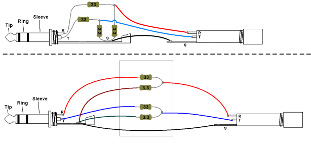
^^^^So in this page this gentleman uses 2x 33R resistors + 2x 3.3R resistors. This results in 35 ohm resistance. The confusion is the 3.3R resistor. Does that scale if I want more resistance or stay the same?
Ideally I want the resistance to be around 330 ohms or more (or slightly less).
So as a result, would my parts be 2x 330R resistors + 2x 33 ohm resistors
OR
2x 330R resistors + 2x 3.3R resistors
Are you talking about this schematic?
In this case, the resistors are in series meaning the amplifier sees a maximum impedance of 33 + 3.3 = 36.3 Ohm.
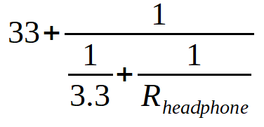
Since the headphone is parallel with the 3.3 Ohm resistor, you would calculate the total impedance (adapter + headphone connected) as such:
330 + 33 is the same in attenuation as 33 + 3.3. Unless you want to run some low impedance headphone off an OTL tube amp, I don’t see a reason to do this.
330 + 3.3 would give you roughly 1/100th the signal, which may result in barely audible volume levels.
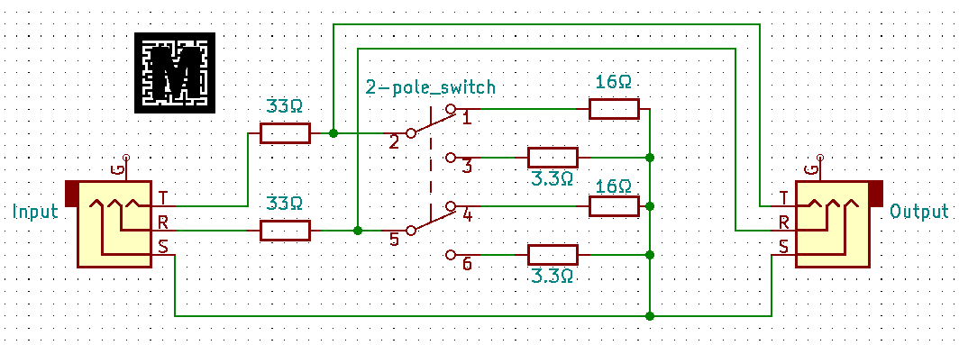
If you are willing to build a slightly bigger device, I would suggest “copping” (=it is a variable voltage divider, no magic in there) the ifi IEMatch.
The 16 Ohm resistors would give you half the output signal, the 3.3 Ohms give you 1/10th
Firstly, thank you for the response! It helped me understand what I was looking at better.
The reason I want to try this at a high resistance is because I have a theory. And hopefully that theory plays out well. But it can only work at high resistances I feel. That’s the hypothesis.
So now, I am a little confused on the 3.3R. Before we go on, I am new to this so please be patient with me if you can.
Do I even need the 3.3 ohm resistor (or the 33 ohm in this case)?
it just seems to be there to be connected to the ground. Can’t I just connect the 330R resistor directly to the ground as well?
Maybe I am misunderstanding the purpose of the 3.3R Resistor in the first place.
I own the DarkVoice and it does get insanely loud but this is not necessarily the reason why I’m trying this.
And yes, I could just simply buy an impedance adapter, but, where’s the fun in that?
Again, thank you for your time!
The circuit is a voltage divider, it reduces the output by 10 fold the headphone is connected across the 3.3 ohm resistor , so it sees 3.3/(33+3.3)*the voltage into the circuit.
Any combination of resistors with the same ratios would do the same thing, but the overall impedance of the circuit would appear different.
The reason for the small resistor value is it is much smaller that the headphone connected in parallel with it, so for the most part the fact the headphone is in parallel doesn’t change the resistance of the overall load much. So it appears as a ~35-36 ohm load to the amp regardless of the impedance of the headphone.
FWIW amps generally are more linear, and have less distortion at lower gain levels.
Adapters like this are designed to let you get the volume control on a device into it’s linear operating range, and to reduce the noise floor on very sensitive headphones/IEM’s.
1 Like
What’s your theory?
Do you know already the output impedance and the attenuation of the system that you want to design?
The circuit is a voltage divider, it reduces the output by 10 fold the headphone is connected across the 3.3 ohm resistor , so it sees 3.3/(33+3.3)*the voltage into the circuit.
Any combination of resistors with the same ratios would do the same thing, but the overall impedance of the circuit would appear different.
So a small deviation from this ratio wouldn’t be a big deal? It would just affect the output reduction by however many fold. Hmm lets say I’m trying to plug a planar headphone into an OTL Tube amp. If I want to avoid heavy distortion by overdriving, I would keep that ratio or increase the ratio. That’s the idea right? Well, and also do something like 20R / (200+20R) OR 10R/ (200R+ 10R)? OTLs are loud and powerful after all.
Examples like these would help me understand better. Thank you again for the response
What’s your theory?
Do you know already the output impedance and the attenuation of the system that you want to design?
The theory is: Can I get a more tube-y sound by making the HD600s artificially 600ohms? That is, using the Impedance adapter in association with the headphones; all plugged into a OTL Tube amp.
The second part to that theory would be, that it must also apply to speakers IF it works that way with headphones.
Keep in mind, even if the sound didn’t get more tube-y, The volume reduction can also work in my favor anyway.
I don’t know what you mean precisely with tube-y sound but you can increase the output impedance (not the headphone impedance) for affect more the frequency response and add a little more bass in the 600 and reducing the volume with a voltage divider may introduce more distortion in otl amps. I suggest to try some tube rolling, if you didn’t, different tubes can really transform the sound and some sounds more tube-y than others.
I own an otl an hd600 and a dt880 600ohm and of course the 880 sounds different but I don’t think sounds more tube-y than the 600