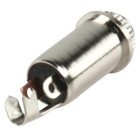
I’m going to mod my DT880 Chrome Edition 250 Ohm so I can have a detachable 3.5mm jack (so I can use the same cables as on other headphones). So far I have found a female jack plug that I want to build into the cup, and I have soldered some wires to it. However I want to have a sanity check with you guys before I continue and cut up my nice pair of headphones.
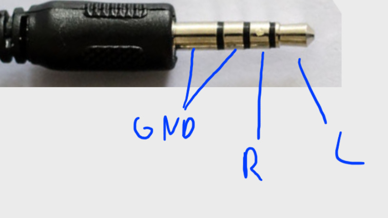
Now I have a jack cable, but it’s a TRRS plug. Now I have found with a multimeter that the three thingies on the chassis correspond to the Tip, Ring and other Ring of the jack cable, so nothing is mapped to the sleeve.
So am I correct in assuming that the tip and first ring of the TRRS cable and the TRS of the attached cables are the same, and that the second ring of the TRRS cable is the same as the sleeve of the TRS cable (and is the ground)?
If so than I can attempt to actually do this tomorrow… or the day after tomorrow, whenever I have found the courage.
This is my first soldering project, so please spare a little prayer for me that I do not ruin my nice headphones.
Can’t help you with the technical stuff, but I modded mine to be balanced and it was also my first soldering. Worked the first time, so don’t be afraid, you can do it
Well, seems like I killed the driver somehow
I had everything soldered and it seemed to work, but when I got to assemble everything and hotglue the connection to the shell the left driver died
Yeah I checked the connection at the soldering point, the signal gets through but the driver does nothing. I probably touched something somehow that I wasn’t supposed to touch. Should be able to order a new driver though.
Great start to the new year
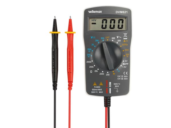
Well I now took it back apart, tried soldering it again and took it back apart again since it didn’t work. If I hold one wire to the ground and one to the right channel, the right driver is activated and produces sound. However if I try the same with the left channel it isn’t working. Also I tried to do this with the original cable, and also with the original cable I can only get the right driver to produce any sound
Yes. When I attach it I get the sleeve to the large bit of the connection and the ring and tip to the smaller. I have already soldered wires to the connection, and when I test it I get a connection between the parts of the jack plug and all of the wires. I even got colored wires so I have brown as sleeve/ground, blue as ring/right and green as tip/left. When I hold the brown cable to the ground and the blue or green to one of the solder points I get sound through the driver. Nothing happens when I hold the brown to the ground and the blue or green to the other solder point.
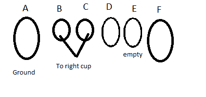
EDIT: This is what the connections on the driver look like.
If I connect brown to A and blue or green to D, I get sound from the right driver. E is empty and always was empty. If I connect brown to A and green or blue to F, I should get sound from the left driver, but that’s not happening.
I do, I tried to check the signal between the cable and the soldered points on the driver and that seems to check out. So when I hold one end of the multimeter to the sleeve and the other to the soldered point of the brown cable it beeps, and the same goes for the ring and the blue soldered point and the tip and the green soldered point.