I get:
A - F: 002
A - D: -000
D - F: 012
What does your meter display when you just put the leads together?
Also: Is there a decimal point?
it says “001”. There’s a decimal if I set it to 200 ohm or 20K (on different places) but not when it’s on 2k.
1 Like
- I HATE manual range selects on multi meters.
- A↔F is direct connection
- A↔D is probably Open circuit (= the two are not connected)
- D↔F is the outlier here (or just bad connection of the probes)
From this thread here:
The interesting ones now are:
B↔A
B↔D
B↔F
BA: 001
BD: 265 (!)
BF: does nothing, just sits at the default 1
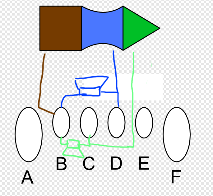
HEY! Driver found!
B is probably Ground, right? So D is where your Tip connection would go.
Well yeah but that would be the Right channel, since B goes to the right driver. Should I not also find two other connections which have +/- 250 Ohm for the left channel?
Whether I put the ring or the tip on D should only control whether I get my left or right channel through my right driver right? I find it a bit odd that F does absolutely nothing, I would expect 250 ohms between F and A as well.
That would be B↔C (like you marked in your drawing)
Still only a right channel I’m afraid  . (Also I get the left channel through my right cup now
  )
)
Though indeed I do get 250 on B <> C.
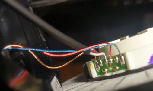
Looking at this guide they soldered the red and white wires both to the left channel of the chassis…?

That is a swapped L/R then.
Wire arrangement should be this here:
(Unless I am making a collosal idiot out of myself or can’t read)
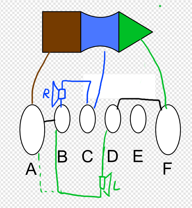
I would use the A and F solder pads because they are connected by the PCB (= black lines) and only have one set of wires on it. Not sure why E pad is not used.
The drawing also relies on your measurements being correct ![]()
Yeah I think I just butchered something. I have now tried pretty much any permutation and it just isn’t happening. In the guide I sent (DT770) They hook up the right channel directly to the connection on the jack chassis, I tried that but all that got me is that my right channel is also no longer working
Thanks for the help though, you’ve taught me a lot!
That would also be an option…
I wonder why it did not work for you ![]()
I get the urge to buy a DT-series just to get my damn drawing right!
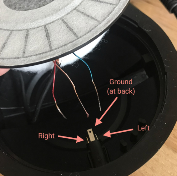
From the guide:
From here:
Connection table with resistanes:
| Cons | A | B | C | D | E | F |
|---|---|---|---|---|---|---|
| A | brown | 0 | (250) | ? | ? | ? |
| B | 0 | right Cup | 250 | ? | 250 ? | x |
| C | 250 | right Cup | ? | ? | ? | |
| D | red | ? | ? | |||
| E | - | ? | ||||
| F | blue |
1 Like
Yeah I shouldn’t have disconnected the shieldet wires that go to the other cup. I can’t seem to solder these, they just melt…
That’s exactly what I had. After a lot of effort I managed to get everything wired up again but still nothing on the left driver. Also because I had so much trouble with the wire of the right cup the solder is now connecting everything to each other, so I can’t get any readings from the multimeter anymore. Right channel is still working though, so I got that going for me.
I think I’ll just order a new driver and see if I can find out what I’m doing wrong with the little cables from the right cup. I’m a bit devastated at my failure though.
Have you got a solder vacuum?
Solder Wick (= Solder Braid) would work too.
Nope, I do use wick to remove it.
Yeah I already did that the first time, I can fix it. However I need to find out a good way to solder that annoying stringy wire from the right cup before I get the new driver. Maybe I should buy some flux and just cover it with flux before soldering?
did you tin the wires?