DT880 Edition non-balanced mode

I know right. So it’s a big rubber thing, in it are 2 shielded wires. I can’t for the life of me seem to strip these wires (I do know how a wire stripper works) which is the first odd thing. When I do manage to get a bit of it stripped, within are a couple strands of copper and a lot of synthetic strands of some sort. These synthetic strands melt a bit and get dark when heated, and I’m having loads of trouble getting solder to stick to it. For the other wires I use regular copper wire which I salvaged from a UTP cable, and this I can solder just fine.

Yes, those cables are a nightmare to strip. I used a disposable razor to VEEEERRRRYYY gently cut around and remove the rubber housing. You also need to remove the synthetic so it’s only the copper.
Keep in mind that when I say gently, whatever you’re thinking oof is still too much force lol.

Even then I STILL stripped some copper along the way, but once you have the copper exposed, you can tin that just fine. So if you have the option of using different cables, it’s worth the peace of mind. Once that is done, they are much easier to solder.

1 Like

I’ll see if I can get that to work when I get the new driver in, hopefully I won’t screw it up again :cold_sweat:.
I’m really curious now to find out what broke, maybe I’ll actually try to disassemble the driver to see if I can find anything.

BTW:
Did you solder those annoying shielded wires back to the driver or did you solder them to the jack-chassis connector thing?

I only removed cables from the drivers, used only the existing cables to solder to the new outputs.
I still have trouble believing you screwed up the driver. There isn’t really anything that can go wrong, unless you remove cables, then maybe.


Don’t judge the soldering job please. It was very neat the first two attempts but in the end I got a bit frustrated.

I did check the resistance again and I do get good measurements now. When I measure the multimeter from the jack to the solder points I get a good connection on all of them. The only thing I find that is not correct is the fact that there’s no sound from the left driver…

1 Like

Is the driver in the picture the left side one?

Because the big difference between your photo and the ones in the guide is these two pads being bridged by solder:

It is, hmm I missed that.

I bridged those two. Tomorrow I will have another good look at the guides, desolder everything but the bridged part and try to connect everything again.

What guide is that picture from? The guide I was looking at looks a bit different.

From this forum. The Lazy Person’s reversible […]-thread.
Keep in mind there are 2 types of connctions to the driver in the DT-series. And 3 is technically all you need.

1 Like

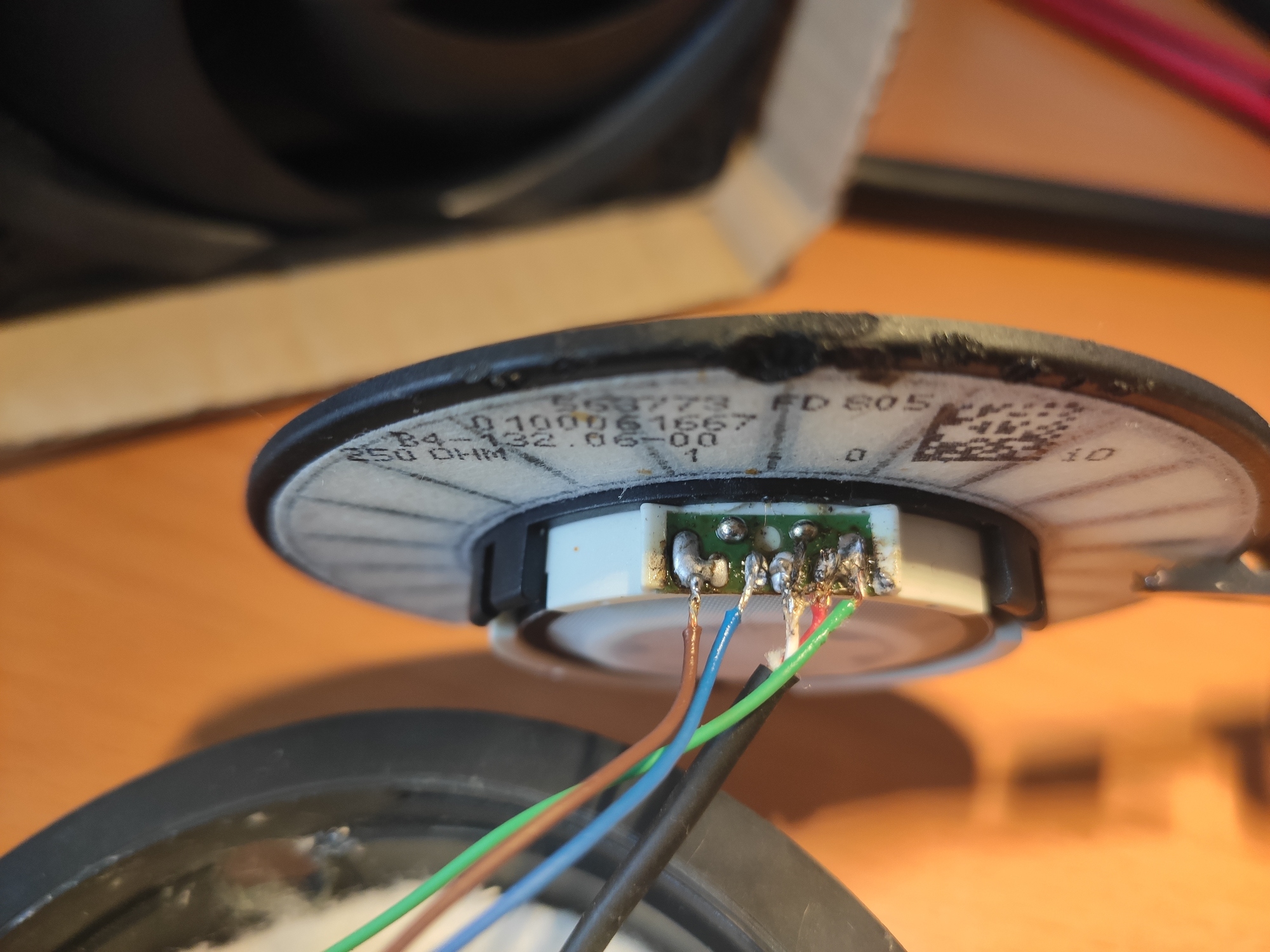
Okay I did it again and I bridged E and F. I used another chassis so the colors are mixed up (sorry). I’m 100% certain I have the right wires connected to the right solder points though.

In another thread (Beyerdynamic DT880 600ohm Balance Mod) I found this image

image
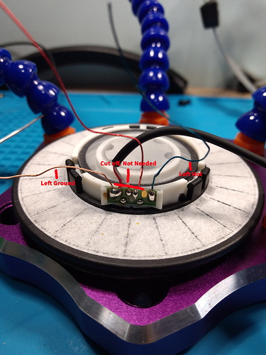
Going by this image I should get music through the left driver by just attaching the left ground and left hot. I know the ground is correct since otherwise the right driver also wouldn’t work, so the problem has the be either with the left driver or the soldering of the left hot. I have tried it with E-F bridged and without E-F bridged, and in both cases there is no music and no resistance when touching left ground and left hot.
With the multimeter I do get a signal if I touch the tip and the left hot solder point, so a connection can get through.

In that other guide I also found this image from the right cup

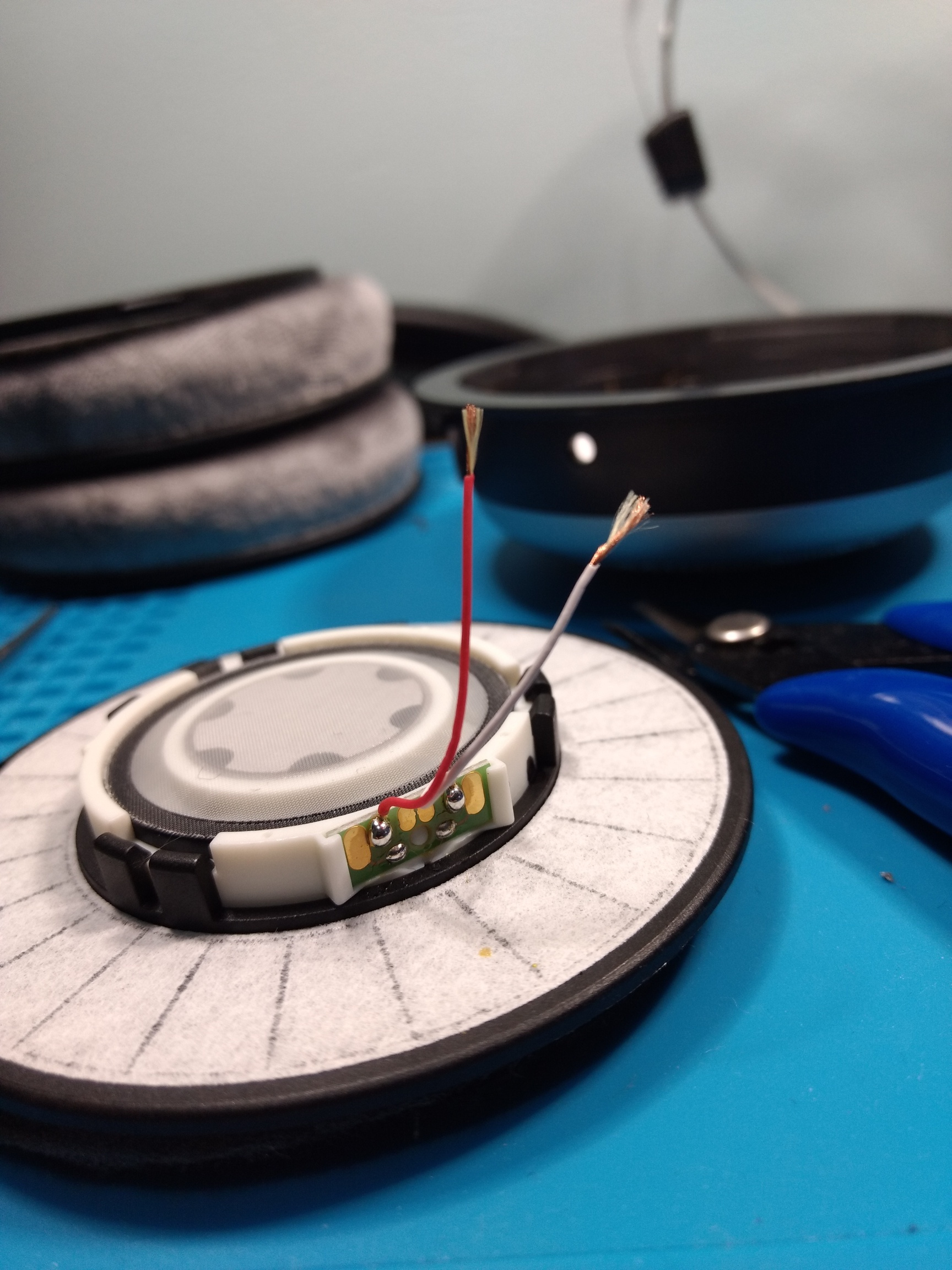
It seems to my untrained eye that the two outer solder points are ground and hot and that the two inner ones are two pass on the signal. So that would confirm that I should get 250Ohm when touching the two outer-most solderpads if the driver was working.

EDIT: This would make sense I guess: if this is correct the solderpads are grouped in 3 pairs of two pads which are close together. Bridging pads close together wouldn’t make a difference since the two righter are both ground, the two center are both positive of the right channel and the two on the left are both positive of the left channel. That could be why you see them sometimes bridged and sometimes not?

I hope I’m not making an idiot of myself, I have 0 experience with this stuff.

gotta be careful, for one there are different versions of driver connections and two, the last tho threads mentioned here are for making a balanced version, which is not what you want. You need a different kind of connection for that as it separates the left and right driver.

When you’re only making the cable detachable you can basically leave the right hand driver alone.
Here are images of what it looked like for me :
With all the cables is the left one, with only two the right

so those of you who know what your doing feel feree to correct me but what I see is the following.
you connect to the speaker on one end and ground on the other. The middle connection on the left is to connect the right side ground to ground (red goes stright to black)
Then the red goes straight to the white for the signal.

For a detachable cable mod you would have done nothing on the drivers and then attach the cables that went out to the new jack. For an unbalanced mod like in those threads, I had to remove the three cables in the middle of the left and then attach to the new connectors.

I never touched the right driver wiring until after it stopped working. The right driver is still working fine, it’s just the left one that isn’t working.
I didn’t use the original wires because they were a pain to work with (or so I’ve heard) and it had a ton of new wires lying around. BTW, I soldered new wires to the shielded wires going to the right driver so they are easier to work with in the future, that seems to work perfectly fine.
Now that I see your picture, however, I do see that it’s completely different from the one I got from the guide that I posted earlier. Your ground is on the right where’s I have it, like in the guide, on the left…

EDIT: I guess it doesn’t really matter if you mirror it, as long as the ground is connected to the ground and the right channel to the right channel and the left channel not to the ground or the right channel it should work just fine.

I don’t know if there is an internal difference. I suppose you could try changing the ground and signal for the left driver. What’s the worst that can happen at this point it still doesn’t work?

I did already try. I also tried on the right driver (without soldering, just touching the wires to the pads) and I do get sound in the order I wired it on the left side. Also it doesn’t seem to matter of you switch the ground and positive.

@MazeFrame @Roknar
Thanks again for all the responses.

SO the problem turned out to be the driver after all. I just got a new one in and installed it, the headphones are working again. They do sound a bit weird but that’s just placebo because I tempered with it myself :stuck_out_tongue: (plus I’ve been listening to other headphones all morning).

I’m quite happy with how they ended up turning out though.

EDIT:
Or could it sound weird because of the new connector messing with the acoustics in the cup? I do have the feeling that this connector interferes a bit the driver in the sense that the driver can’t go all the way down in the cup since it’s blocked by the connector. I don’t have to force anything when reassembling though…

2 Likes

Update on this:
I am using a trrs cable since I don’t own a separate trs cable and I use this one for my MH752.
I just noticed that the volume is decreased and that the headphones sound better if I don’t fully insert the Jack plug into my amplifier. I figured the extra ring wouldn’t make any difference, but I was very wrong. Luckily it seems the headphones are 100% OK, I just need a new cable :smiley:.
When I fully insert the jack the volume goes up a lot and the sound gets more metallic I guess.

EDIT:
Found a TRS jack and it’s exactly the same, sounds better if I don’t plug it in all the way into the amp. No idea what’s going on…

1 Like

@Roknar @MazeFrame

Well I just made an interesting discovery. When I go into pulse audio (APO for Linux pretty much) and reverse the polarity of either the right channel OR the left channel, it sounds right again… It seems I have hooked it up incorrectly after all, now the question is, do I reverse the polarity of the right channel (by switching the red and white wire going to the right driver) which is very easy to do, or do I inverse the polarity of the left driver, which would require quite a bit more work. Does it matter whether the polarity is inversed, or is it only important that the polarity is the same for both sides?

Also, looking back at the pictures in this thread:
This is what my left driver looks like:
image

This is not:

I guess number two is what it should look like, though I hope I can fix this by just switching the red and white wire going to the right cup (so the extra shielded one).

1 Like

That… is… quite the finding.
I would have never guessed something like that.

To 95% of all audiophiles, inverse or not makes no difference.

The important part electrically is to have both drivers hooked up in the same phase (either 0° or 180°).
Else you present weird loads to the amplifier depending on the L/R balance, which as you found out, is a real world problem.

1 Like

Yeah I tried screwing around in pulse effects but couldn’t notice a difference between Left Inverted or Right Inverted, as long as I inverted one. I’ll invert the right channel since it’s way less work and therefore less risk of breaking something.

I was really surprised to, but this also explains why it was sounding “normal” when I pulled the plug halfway out of the connector, since I only got the right channel but in both ears (6.3mm jack).

Thanks for all your help man, really appreciate it! :grinning: