Part 2
Components in Circuit
Warning: Voltages above 30V are dangerous.
(With enough effort, a sweaty teashirt and car battery can kill, different story ![]() )
)
Important tools
When working with or near electronics, there are some important and some nice to have tools.
-
Multimeter - Resistance, Voltage, Current, sometimes Capacitance and Temperature measurement device in one. Way better than one of those glowing screw drivers at determining if a circuit is live (as in: Can make you dead).
-
Size 1 Philips Head - Gets you into most devices, like your multimeter when you blew a fuse because you set it to mA when dealing with A.
Insulated ones are nice, sometimes don’t get into tight spots. Only take stuff apart that is unplugged! -
Replacement Fuses for your Multimeter - No shame in taking the thing apart to replace a blown fuse. Never buy just one! And avoid the glass tube ones. Under extreme fault conditions (= shit hitting the fan), the wire evaporates coating the glas making it conductive causing a minor explosion.
-
Soldering Iron - No need to own a Weller Rework Station when you solder two cables back into their plugs a year. Workable soldering irons can be had for 20 bucks.
I saw people do this: The shiny end gets HOT! Do Not Touch That!
Optional Tools
-
Known Working USB charger - When troubleshooting a phone not charging, having a known good USB charger (and cable) on hand helps a ton. Can also use your multimeter to determine if the wall socket has power.
-
Flashlight - For that extra bit of light
-
Magnifying glass & Inspection mirror - For small and tight spots
-
Grounding wrist strap - For ease of mind when dealing with expensive electronics. In Europe, most sockets have a grounding pin or grounding springs to clamp to. Alternatively a water tap or plugged in computer (not a notebook) also work as grounding points.
Toaster Timer
While you could use a bimetal strip and screw to do heat-based timing or a microcontroller there is also a super simple analog circuit to achieve the same.
Note: Do not implement this 1:1 as I “just winged” this circuit from what I remember building.
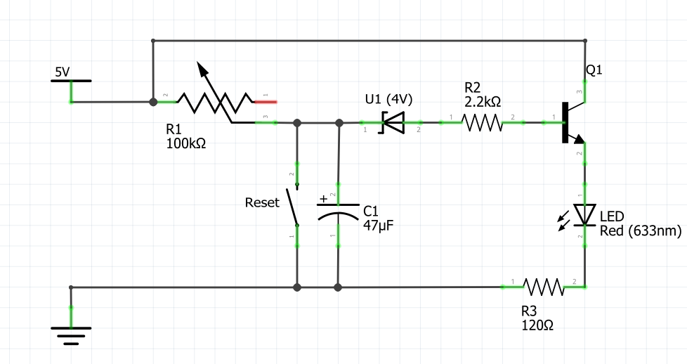
Operating principle:
The 5V supply charges the Capacitor C1 via the Variable Resistor R1, when C1 reaches 4V, the Zener-Diode U1 allowes the Transistor Q1 to pass current through the LED.
R2 and R3 are to protect the Transistor or LED against too high currents.
The reset switch discharges the capacitor reseting the timer.
Blinking Lights
Very common circuit is to have two LEDs blinking. Running of a 9V battery and built from 10 components, it just blinks back and forth.
Operating Principle:
The capacitor C1 controlls the state of Transistor TR2 and vice versa. A Transistor turning on means it discharges its Capacitor turning the “opposing” Transistor off.
In other words: This is an astable multi vibrator, no state is stable and it has multiple states.
Circuit design and build guide source
Ohms Law
Ohms law is simple: Resistance = Voltage / Current
This simple formula by applying simple maths can be made into two variations:
- Voltage = Current * Resistance
- Current = Voltage / Resistance
You may ask why this is such a big deal.
Picture this: Your multimeter does only measure current and voltage. How do you determine the resistance of your headphones?
Take a AA (or AAA) battery (which can be yanked from a flashlight or remote), measure its voltage and write it down.
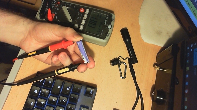
Now touch the tip of your headphone jack to the battery, then use the test leads of your multimeter to complete the circuit in current mode.
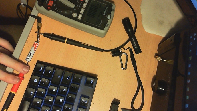
You end up with a voltage (about 1.3V) and a current (anything from about 0.3A down to 0.002A). And just like that, you know the resistance of your headphones!
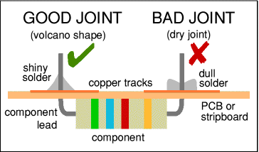
Basic Soldering Guide
- Clean workplace, preferably a piece of wood to protect the table (or carpet)
- Clean Tip = Good Tip - Don’t use your soldering iron to shrink heatshrink, please!
- Flux is your friend. That small puff of smoke when touching the solder to the iron is what makes the joint work. You can also dunk blank cable ends into flux or use a syringe to apply some to the PCB you are working on.
- Heat the parts you want to solder, then touch the solder to the joint.
- Let the joint cool on its own. No blowing on it or drenching it in the sink.
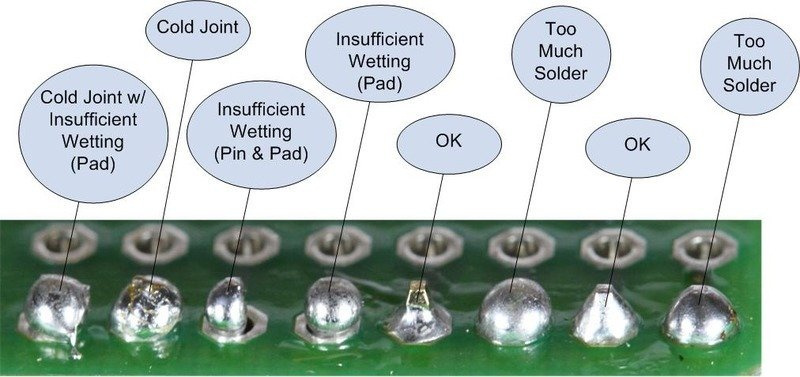
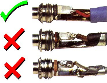
Is my solder job good?
What does your multimeter say?
Resistances greater than 0.1 Ohm (idealy 0 Ohm) are reason for concern.
How does it look?
It should be a clean shiny surface surrounding the wire or pin comletly without being a massive ball of metal.