I hope to shine some light on the various electronic components found in the devices we use daily.
This is by no means a complete explanation, there are books about electronic basics if anyone is intersted to expand their knowledge.
To keep this understandable, I will stick to DC circuits. Formulas are easier to handle, behaviour of components is “obvious” and you can trace the flow of electrons with your finger.
There are two major groups of components:
Passive Components
Passive components are all the ones that “just do their thing”. Such components include:
- Resistors
- Potentiometers and Trimmers
- Capacitors
- Coils and Inductors
- Transformers
- Oscillators and Crystalls
Active Components
Active components are all the ones that “influence” circuit behaviour by switching of some kind.
- Diodes, Rectifiers,
- LEDs, Photodiodes
- Optocouplers
- Transistors, FETs, Triacs
- Piezo elements
- Tubes (Valves)
- ICs (= Integrated Circuits)
Important Units
-
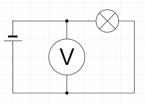
Volt - Named after Alessandro Volta, this SI-Unit describes the electric potential. Think of Volt as a Lake on a Hill. The higher the Hill, the higher the energy the Water can release.
Volt V is commonly symbolized by U in formulas. -
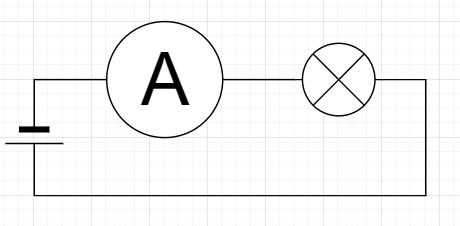
Ampere - Also named after a scientist (André-Marie Ampère), this SI-Unit describes the flow of electrons. Think of this as the mass of water in a river.
Ampere A in formulas is writen as I -
Watt - Named after James Watt, this SI-Unit describes power. It is the product of Current times Voltage. Wattage W in formulas is writen as P
-
Ohm - Named after Georg Simon Ohm, is the SI-Unit of electrical resistance. Resistance Ω is writen as R in formulas
Other important Names&Acronyms
-
Ground (= GND) - The 0 point of the circuit.
-
Power (sometimes: Rail or V+/V-) - Source of power. Can be positive or negative in respect to GND.
-
Source - Signal source, external input to the circuit.
-
SMD - Surface Mount Device, these components that are soldered to the top of a circuit board. As opposed to through hole components which have “legs” that stick through the PCB
-
PCB - Printed Circuit Board (sometimes PC-Board), the card holding components in place and connecting them. Simple PCBs have 1 layer, the most complex ones as of 2020 have 9.
With the fundamentals covered, lets have an indepth look at the various
Components
**Resistors** Resistors are probably the most basic component. They resist the flow of current causing a voltage drop over them.
These guys come in any shapes and sizes (and power ratings), from smaller than a grain of rice to heavy water cooled variants.
In a schematic these can be represented by one of two symbols (the box is the new IEC symbol):
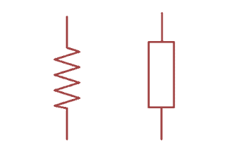
In the wild, you typically find resistors in these shapes:
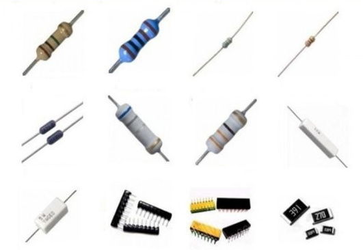
Source
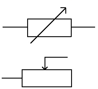
A special type of resistor are Potentiometers (= Pot) and Trimmers. These are variable resistors.
A potentiometer is between Source and Ground providing a reference in respect to the two. While technically the same, Trimmers are not rated to frequent adjustment.
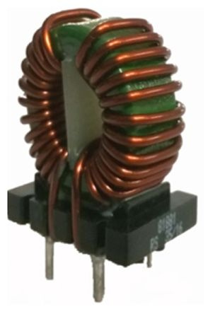
Note: “This Resistor is green!” → Could be an inductor. More on those further below.
Capacitors
These components resist a change in Voltage, meaning raising or lowering it will be delayed.
If you think of electricity like water, a capacitor is like a tank, the larger the surface, the more water you can drain before a level change.
It is important to note that not all capacitors are okay with reverse polarity. Any polarised capacitor hooked in reverse or to AC is a potential fire hazard on top of releasing toxic gases.
Difference between Capacitors and Batteries:
Capacitors store electricity as an electric charge, Batteries store it as chemical energy.
The Symbols and their respective Parts:
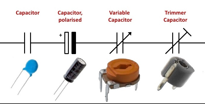
Source
Inductors
Similar to how capacitors resist a change in voltage, Inductors and other coils resist a change in Current.
In the water model, this would be like water moving (or not moving) through a pipe. Just like slamming the water tap shut will cause a water hammer, or a voltage spike (= current still going = raise in voltage) in an inductor.
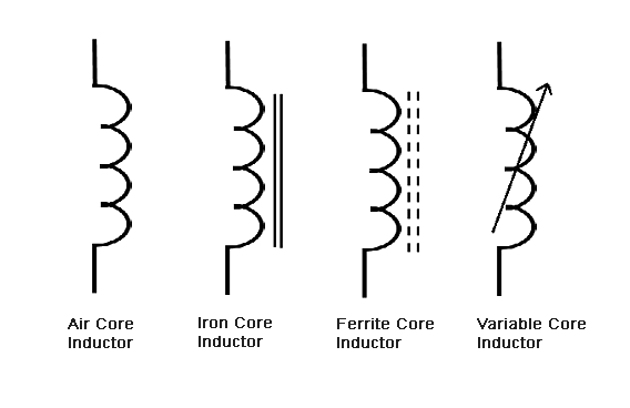
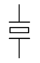
In a schematic, an inductor will look like one of these (mostly ignoring the core material, two lines means core ![]() ):
):
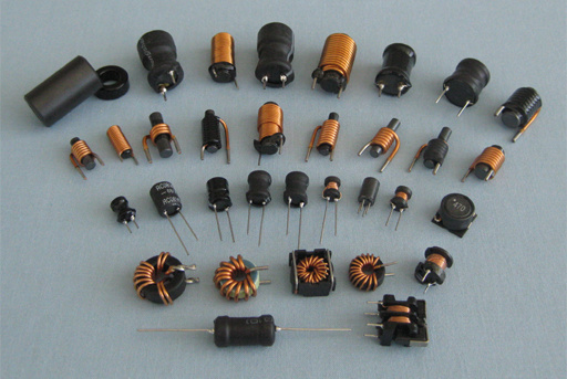
In the wild:
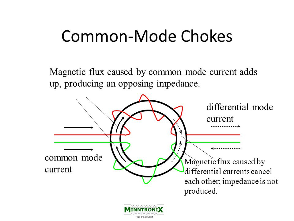
A special type of inductor is the Common Mode Choke. These take advantage of current flowing in and out of an area causing magnetic fields that cancel each other posing very low resistance to DC. Noise arriving on both lines causes opposing magnetic fields that then block the noise from entering (or leaving) a section.
Working principle:
Symbol:
In the wild:
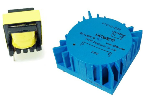
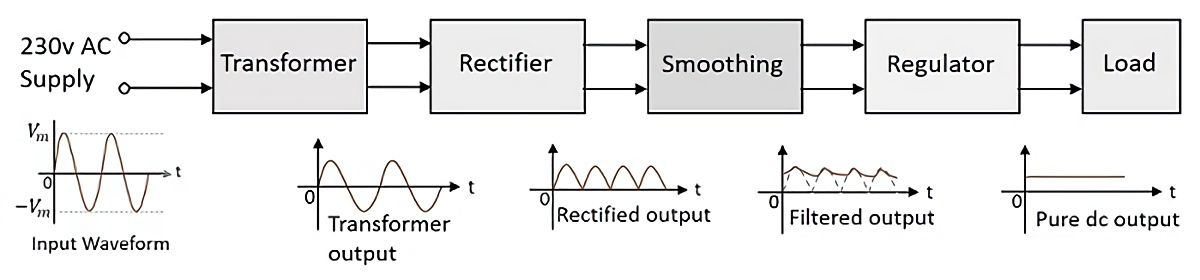
Transformers
When you put a second (or third, or even more) coils into an inductor, you get a Transformer.
The ratio of windings on either side results in different voltages. Transformers ONLY work with AC.
There are many ways to build these, depending on application. A few types:
-
Isolation Transformer - 1:1 Ratio isolates the two sides electrically
-
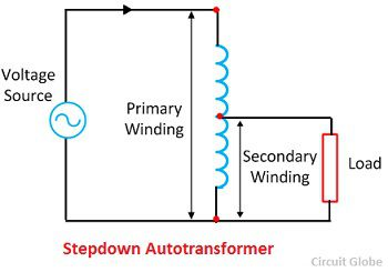
Auto-Transformer - Variable Ratio, allowes dynamically adjusting the voltage of the output side
-
Center-Tapped, Generates multiple voltage levels. Often found in audio gear because Op-Amps often like running of -12 and +12 in respect to Gnd.
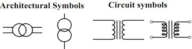
Symbols:
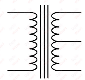
Center-Tapped:
Auto-Transformer:
In the wild:
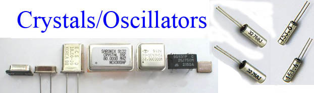
Oscillators and Crystals
When supplied with a voltage, these things oscillate with a specified frequency. Useful when the integrated timer in an IC is not precise enough for time keeping or synchronizing.
These things are available in nearly any frequency one could desire. In combination with a counter, even the impossible frequencies can be achieved ![]() .
.
Symbol:
In the wild:
Source
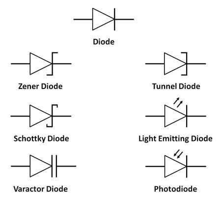
Diodes
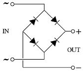
A “normal” Diode is an electronic check valve. It only allowes current to flow in one direction and blocks it in reverse. The cost of this is a small voltage drop due to the semi-conductor inside (usually 0.8V).
Schottky-Diodes perform the same function, have a faster response time and lower voltage drop. Slightly increased price tag for the service.
Zener-Diodes allow current to pass in reverse when a certain voltage threshold is reached.
Tunnel-Diodes are highly specialized and I have no idea what uses for these things are.
Photo Diodes generate current depending on the light hitting them.
LEDs - Light Emitting Diodes do exactly what the name implies. Reverse polarity, high currents and over-temperature should be avoided to prevent damage.
OLEDs are similar (O for organic), I have never worked with these.
Laser Diode - Emits laser light (= single frequency light) usually from a crystal when current passes through them.
Symbols:
In the wild:
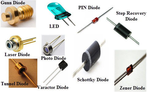
Source
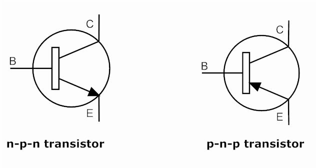
Transistors
By applying a voltage to the Base, current can flow from the Collector to the Emitter. In simple words: An electrically operated switch.
These things can switch way quicker than any mechanical switch ever could (8 GHz anyone?) and the lack of mechanical contacts allowes for near infinite switching cycles.
Symbol:
In the wild:
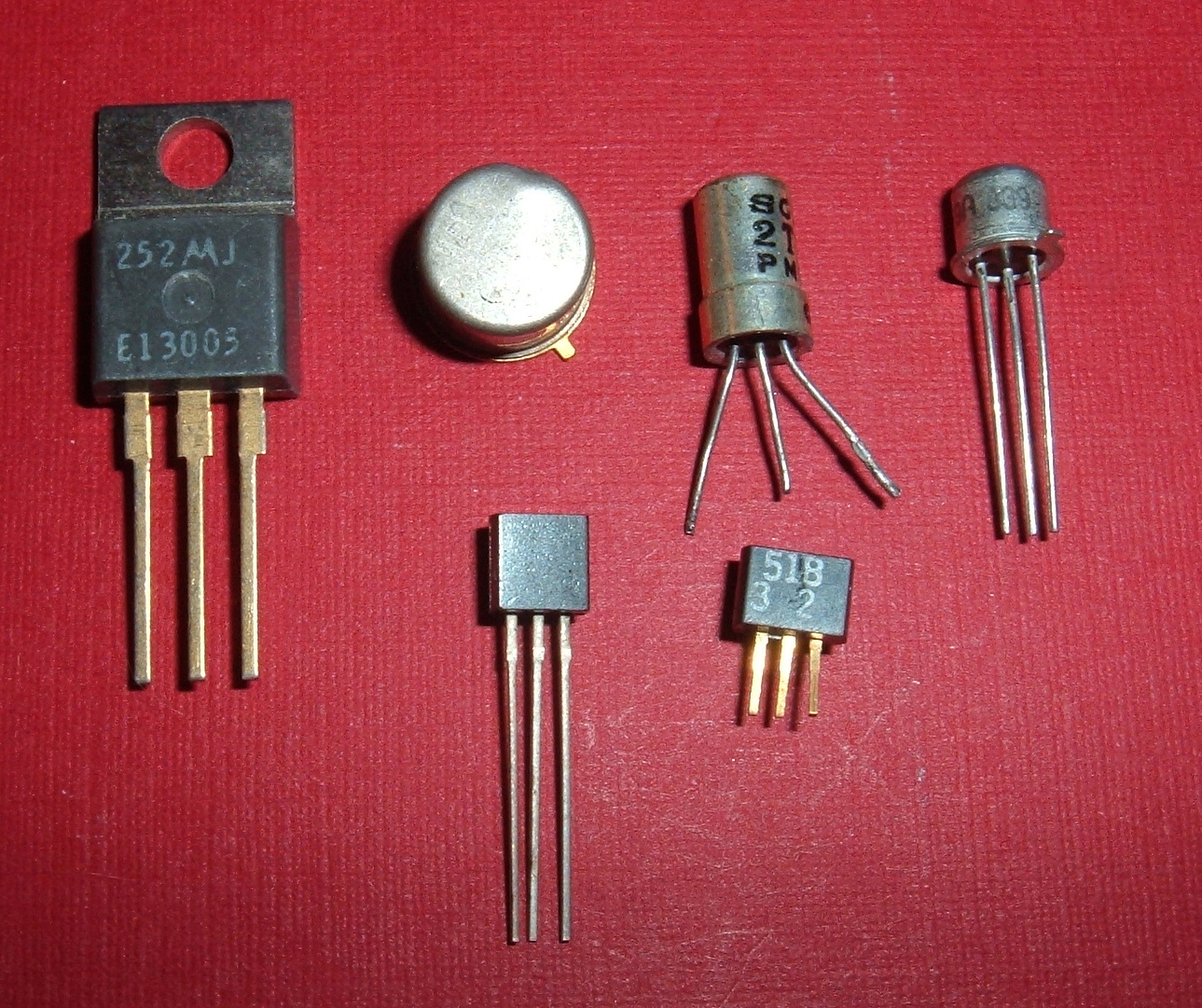
Source
Similar to Transistors are Triacs. These perform the same task as transistors, except they can switch AC.
FETs are a type of Transistor, the most well known arguable being MOSFETs.
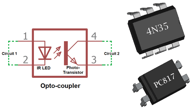
Optocouplers:
When you combine an LED and a Photo Diode (or Photo Transistor) into one unit, you get an Opto-Coupler. These little chips allow to monitor the state of the other side without having an electrical connection.
Tubes
Exist in many different sizes, for switching, rectification or amplification tasks. Basically the father of modern semi-conductors.
The basic working principle is that the heating element generates an electron cloud wich will then flow towards the positive end. The vaccuum is needed to allow for a free flow of those electrons.
Adding what is called grid enables control of the electroon flow making the tube a switch.
ICs (Integrated Circuits)
This is where the fun begins!
Imagine having a complete circuit, but instead of it being the size of a toaster, it is a small 14-pin chip.
The “legs” (= pins) are connected to the circuit inside the plastic (or ceramic or metal) packaging.
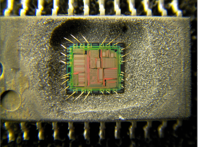
You can find functions from power monitoring, battery management, amplification, storage, and many more as ICs. So consult spec sheets before randomly ordering a collection of theses ![]()
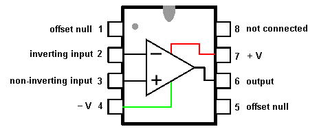
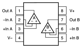
The most common type of IC arround an audio forum is probably an Op-Amp in an 8-pin DIP package. To make matters a little more complicated, there are dual and single Op-Amps in these packages.
The notch marks the pin 1-8 end.
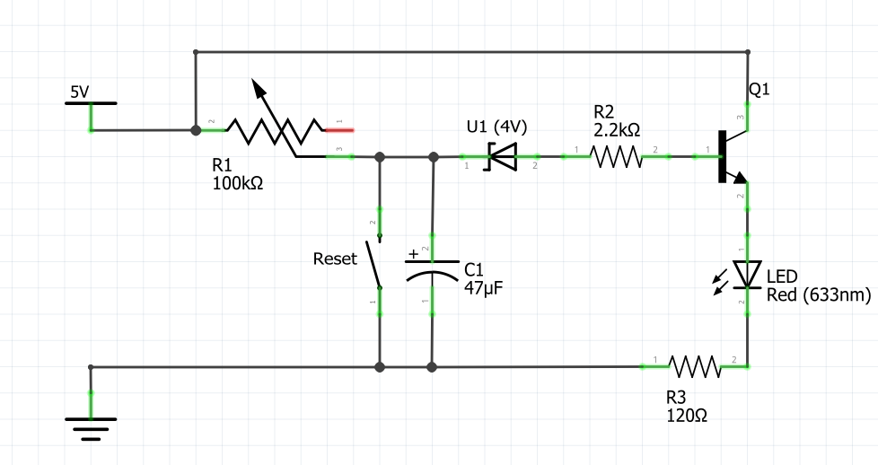
And with this, you now have an overview of all the basic parts that make up electronic circuits. My next post will include some basic formulas and circuit drawings to show these parts in actions.


")


