I have 2 topping a50s(not S). Both have a poor 2.5mm input. Looses contact when cable moves.
Would like to replace 2.5mm jack. I am a novice but do have a little knowledge and a soldering kit.
I know sounds dangerous doesn’t it! Any advice,tips or tricks. They are under warranty but
do not want to ship to China! Any help would be very much appreciated.
What exactly do you need help with?
Is replacing a balanced 2.5mm jack very different than a non balanced? Are there 2,3 or 4 solder points?
The a50 is very compact. I have to disassemble the entire unit just to get to the jack.
No tear down guides online. Just hoping to get an idea of what to expect.
Most PCB-mount jack connectors (3.5mm, 3 contact) are 4 pole for presence detection.
I have also seen 3-contact sockets with 5 pins.
From the few photos available online, I would guess there are screws on the underside in the corners, likely hidden under the feet.
Note: Depending on internal layout, it may be easier to run some wires from the position of the old jack and drill a hole for a new one further away from the PCB.
OK. Thank you. I will take a look.
The first thing to do is open it and check if the connector is a through hole connector or a surface mount if is through hole it’s pretty simple to desolder and replace you need just a solder sucker to remove most of the solder and some desoldering wire to clean up the PCB before replace the connector. If is a surface mount the soldering process is more challenging for someone without much experience. About the connector is a 4 pin
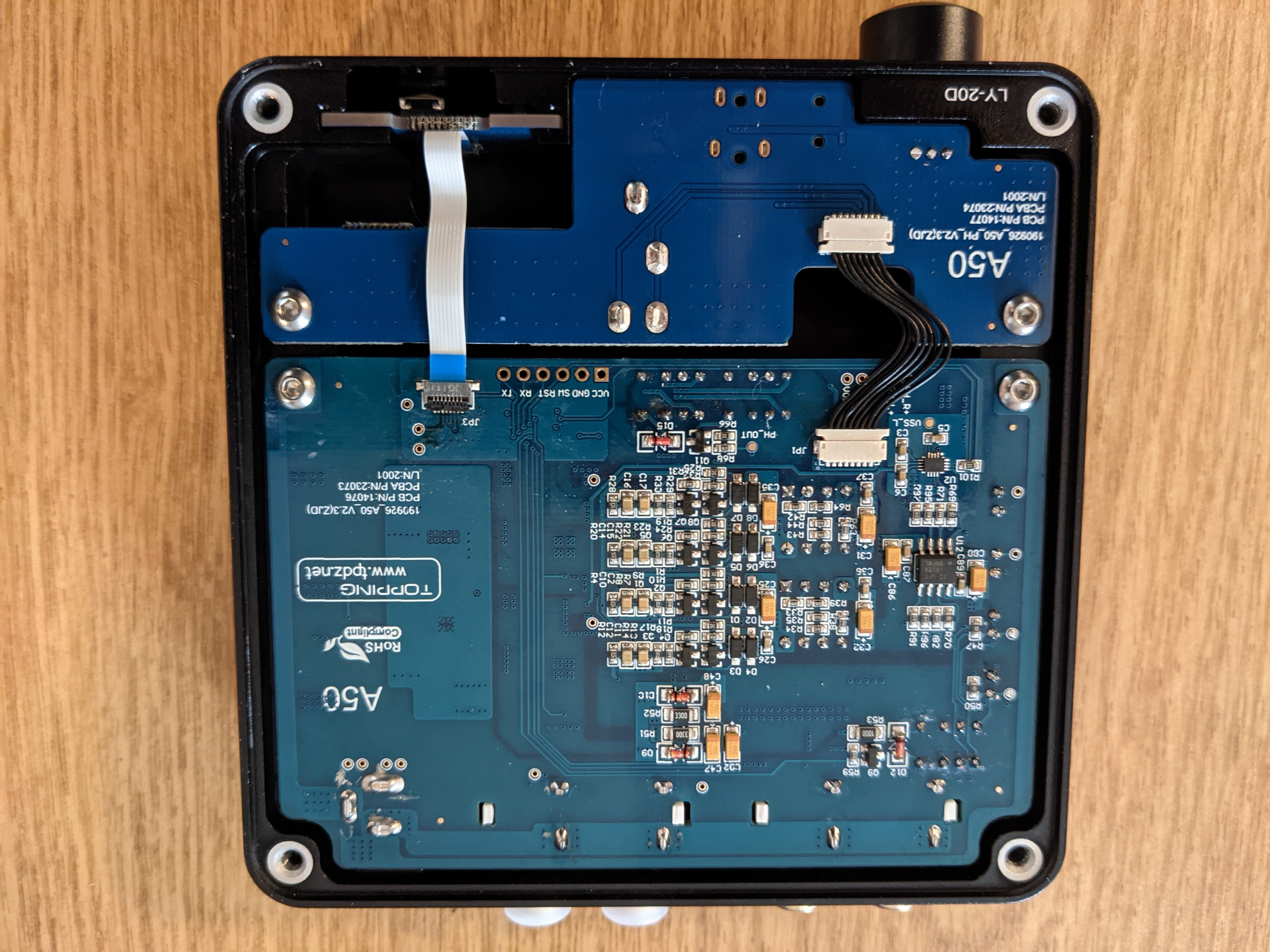
This is what I see! I am a little intimidated by how compact it is!
If it’s PCB mounted and you can actually source a replacement that’s the same size, the best advice I can give is find someone who’s desoldered things before.
Rigid PCB mounted devices are IME a pain in the ass to desolder, and remove cleanly.
Yep. Starting to think this is out of my ability. Know anyone in the community that does this kind of work?
You should disconnect the flat cable gently unlocking it first and after remove the 2 screws so you can flip the small PCB on the top and be sure at 100% that the connector is a surface mount. But from what I can tell from the picture and the probably location of the connector it is a surface mount.
I’ll give it a shot. I appreciate your help
You’re welcome, if you don’t have experience with the surface mount components I suggest to watch some video online so you can understand better how to dial with it and with what you are dealing with before decide if proceed, the only positive thing is that the contacts of a surface mount connector are not microscopic like most of the SMT component so is one of the simplest STM component to solder.
That looks doable, actually.
Order of operation:
-
Using a pair of pliers/tweezers/etc. , pull on the blue tap, NOT the cable!
-
Stick a flat blade screwdriver in from the sides and gently push the connector out of the receptacle
-
Lastly, take out the screws.
To get the daughter board out, you may have to pull the knob of the potentiometer shaft.
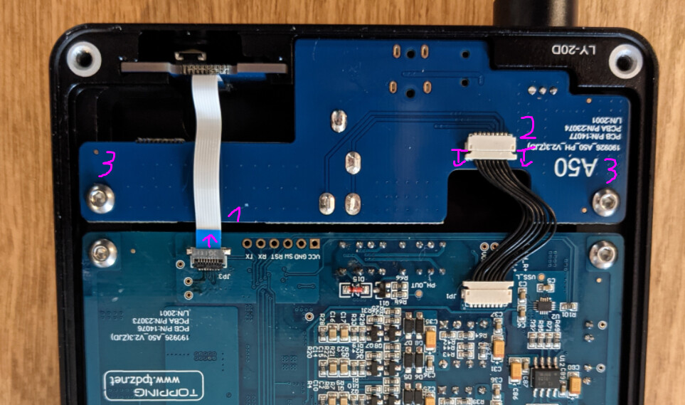
Just remember to unlock the cable first by gently pushing the 2 small white plastic L beside the cable
Wow. Thank you for the guide!
Thank you!
You guys are great
While in there, would you mind taking some more photos?