Electronics 101

This post here is mainly to bump this thread up a bit. Also shows you what lightning does to your electronics:

Next regular post in this here will be Multimeter, Measuring basics and Safety

Part 3

Multimeter basics

:warning: Warning: Voltages above 30V are dangerous.

Introduction
A good multimeter does not have to cost a fortune. If you need one twice a year, don’t shell out $200.
I would recommend to buy one with detachable leads so you can hook up the right probe for the right job.

Most cheap multimeters have 3 settings:

  • Voltage
  • Current
  • Resistance (included Continuity)

Other functions you may find:
  • Diode Test
  • Capacitance (hit & miss in my experience)
  • Inductance (Multimeter ≠ Inductance meter, very different devices)
  • Temperature (using a thermocouple, often with an adapter)
  • Frequency Counter (hit & miss in my experience)
  • Transistor tester (what for? Don’t you have a datasheet?)

  • Max/Min Function
  • Hold (Flukes Auto-Hold is :100:)
  • Backlight
  • Range Adjust

Measureing

Range selection
When your meter does not do this automatically, you select the range that includes the highest value you expect.
Note that when measureing current, the inrush current may be a lot higher than current while the load is running.

To throw all beginners into the deep end, welcome to the bastard meter from hell:

90V is the outer one.
20V is the center scale.
For 10A, you have to take the same scale as 20V, but divide by 2. And the 1A scale is the inner one, divided by 10. Don’t laugh, I have seen this in the wild!

The only good feature of this example piece is the fact it requires you to plug the probes from Black&Blue for volts to Green&Black for Amps.
There are meters that shutter the incorrect ports so you don’t blow up fuses (Gossen Metrawatt does this on a lot of their meters).

Do yourself a favour, buy a good meter.

Probing
Do get good results, you need good contact. The manual probes will often be “good enough” for resistances or finding if there is voltage presend. For everything beyond that, you want alligator clamps, screw terminals, 4mm hookups, etc.
That way your fingers (and body) don’t skew the results or put your heart and lungs into the line of fire.

:warning: When Probing arround >30V, use shielded test leads like the ones below. Only use 1 hand to hold the probes, the other hand holds the meter.


↑ Honestly though, use clamps/plugs to hook up and don’t even touch whatever you measure.


Correct Meter Positioning

Current (A) - Your meter will be in series with the load. In this example, a light bulb.
image
This is also how you measure resistance, capacitance, etc. Just without the battey in circuit.

Voltage (V) - Your meter will be in parallel with the load.
image

:exclamation: Urgent Advice: After EVERY use, plug the leads back to measure volts.
That way you will not blow up your meter or the fuses inside it by accident.


Purchase advice

You want a True-RMS (= TRMS) meter, simply because these types of meter can measure AC.

The measurement leads should have guards so your fingers don’t slip into the danger zone.
Fluke TL 75 for example:
image

Analogue vs Digital
I find analog meters to be way too much hassle. The neelde is never readable, accuracy is at the mercy of correctly positioning the meter and there are multiple scales of which you have to read the right one.
Buy a digital meter and you are set, even when holding the meter at wierd angles.


Autorange vs Manual
Do you want to think about the highest value you could see?
Do you want to step through the ranges until you get a usefull measurement?
Are you mad?

Answered any of the above questions with yes, then get a Manual one. All the normal people, save yourself the hassle and get an auto-ranging one.


Brands that won’t blow up in your face:


Misc Advice

Help! My meter does not measure amps!
→ Have you checked you got the test leads plugged in correctly?
→ Correct range selected?
→ Still nope? You blew a fuse. Time to open the battery cover (or the entire meter) and replace it

Fuses
You want ceramic fuses in all your devices, especially the multimeter you have in your hand.

The good ones are filled with a fine sand that will take up the metal vapour under extreme fault conditions interrupting the current flow. Glas fuses may cover their insides in metal, which will then conduct making them explode.
Video showcasing fuses under fault conditions

6 Likes

Anyone interested in nearly 25 Minutes of electronics nerdery?

1 Like

Part 4

Understanding Power Supplies

Introduction
Most equipment runs on less than grid voltage (110 to 240V, depending where you live). In order to not make itself explode, most electronic devices use a power supply of sorts.
The idea is to turn whatever comes in into the desired voltage(s) while keeping EMI from the grid out and EMI caused by internal happenings inside.

Linear Power Supplies
These are the more traditional PSUs. Efficiency is not great, size and weight are bad. They don’t introduce more ripple to the power though.

Putting the incomming AC from the grid into a transformers primary winding will give you an electrically isolated voltage. Depending on the ratio between primary and secondary, a lower, equal or higher voltage than incomming.
Depending on the transformer, you now have a lower voltage AC.

By using 4 diodes in the following arrangement, you can now turn your AC into choppy DC.
image

After the rectifier, you probably want to add some capacitors to smooth out the choppy DC. Some additional filtering using chokes to catch higher frequencies that passed through the primary transformer could not hurt either.

Now it is time to hand our almost desired DC to a linear regulator (or several of them).
Due to their working principle, they reduce the remaining ripple even further and provide a clean stable DC for your circuit to work with.

As a block diagramm, a linear PSU looks like this:


Source

Pros and Cons of Linear PSUs

Pro Cons
Simple Circuit Inefficent, Linear Regulators are by design inefficent
Reliable, this is largely because of their simplicity Size/Weight, due to how transformers behave, the low frequency requires “big copper”
Low Noise, the only “noise” they produce is the 50/60 Hz from the grid (or double that after the rectifier)

Switch Mode Power Supplies
What if instead of having the transformer first, you had the rectifier first?

That is exactly what a Switch Mode Supply does.
Step 1 is to rectify the incomming AC doubling its voltage in respect to Ground. They also put a filter stage here because the next stage produces nasty EMI that can’t make its way to the grid.

Now comes a switching element like a MOSFET. This will be used to run the transformer at the frequency we want and only when we want. Keep this in mind for later.

After the switching element followes the transformer. As we can run it at any frequency we want, it can be relatively small and the winding ratio does not matter as much (it still is important).

After this transformer, we need a diode and some filtering including some capacitors (don’t need them nearly as big as in a linear supply due to the high frequency of the transformer) and an inductor to keep EMI in check.


Resonant Switch Supplies
These PSUs are a relatively recent development as they require very fast switching components. Their claim to fame is very high efficency upwards of 90% achieved by switching at the zero-crossings of the incomming sine wave.
So instead of a “dumb” passive diode rectifier, these PSUs have active rectifiers (there are reverse protection diodes in the MOSFETs, different topic).

I could not find a graphic with the wave forms for each stage plotted. :frowning:

2 Likes

Some “applied electronics”:

I feel like I may need to introduce you to old fashioned spice that COULD show you waveforms of that system quite easily.

1 Like

I could certainly rig up a schematic and simulate one.
Question is if that is not beyond the scope of a beginners electronics thread.

I even kicked out capacitive dropers from the PSU post to keep it relevant to audio gear.

Hi guys, this is an interesting thread tbh.
I study electrical engineering, just gotta pass the calculus 1 and the first semester is done

But i was just wondering

How do the components of hybrid or multi-driver IEMs work?
Are the crossovers just systems of small capacitors and inductors?
Do they have to put resistors in front of lower impedance transducers?
Sooo many questions, not many people to answer


2 Likes

Damn successful first semester. Congrats.

Could be. MLCC’s exist in surprising capacities. Not sure about Ferrite beads.

There are probably some IEMs in clear enough cases to get an idea what is going on.

2 Likes

To not derail the GL2000 thread, I brought you here :wink:

Looking for a simple answer to a simple question, that may sound right.

Problem is two fold:

  1. Depending on the inner workings on the amp (I wrote an overview of all but the Op-Amp based ones here), you may have a linear power to load impedance, except for two power spikes into 50 and 200 Ohm.

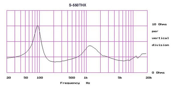
  2. Voice coils, Ribbons and Planar drivers do not present a linear impedance. In fact, the impedance may be a mountain range similar to the frequency response.
    Example:
    image
    Source


Don’t get me wrong, guestimating the SPL an amp can get out of a speaker/headphone using a spreadsheet is perfectly valid.
As you said yourself, loud ≠ quality


The Correct-ish Method
I have tried to measure power into a headphone.
Setup was less than ideal as I had a lot of probe leads dangling around acting as antennas, I have no LCR-meter on hand to verify AC-characteristics of the precision resistor I had in series with the drivers and the Oscilloscope I have on loan is a bit slow on the FFT.

The results were as expected: Shite
Learned a lot in trying though.

1 Like

I wasn’t trying to give the most scientific answer here. To be fair, most members of this forum don’t even know what a OHM is. I find that if you give really complicated answers here, people eyes just glaze over and they ignore your post. I’m not saying you’re wrong. I was giving an easy method that could help those that think that Loud = Good.

This community found a good balance between objective and subjective audiophilia.

And as tubes are somewhat popular on here (most OTL tube amps don’t play well with low impedance headphones), I think most people here know what resistance (and by extension, impedance) is.


Then word it in a way that is understandable?
If my answer relied on pretending to be the smartest person in the room, then I would reconsider the wording of said answer.

Except I did word my original post in an easier to understand way. You came in and complicated it and thought you were smarter by replying in the 101 thread. You literally just did the thing you said you don’t do.

This thread is my attempt at pulling back the magic veil that somehow surrounds everyday devices.
I am nowhere near as good at breaking down big and complex issues into understandable and relatable bits as people like Louis Rossman or Tarah Wheeler when it comes to Right to Repair.


I despise incorrectness in the name of providing a simple answer!
Like I said, explain the problem in an understandable way that does not rely on words to make you seem smart.
Given your reaction, I am not sure if you don’t understand me from a knowledge point or I worded it poorly.

Yes i is dumb. you no hypocrite me sorrrryyyy

Part 5

Power, Sensitivity and Impedance

:warning: For ease of explanation, I will write this for DC circuits. As such I will use resistance and impedance interchangeably. Audio is off course AC.

This part aims to explain how to evaluate if your amplifier can properly drive your speaker or more commonly, headphone. There are some assumptions on my part that I (hopefully) mark clearly.


Units and Vocabulary
In Part 2 of this thread, I touched briefly on Ohm’s Law. Short refresher:

Power (in Watt) is Current (in Ampere) times Voltage (in Volt)
Voltage (V) equals Current (A) times Resistance (Ω), or squre root of Power (W) times Resistance (Ω)

Sensitivity in dB per W (the lower case “m” often found before the W is the metric prefix for 10^-3)

Decibel (the lower case “d” is also a metric prefix, the unit is “Bel”) is used to describe ratios. It is logarithmic meaning for each 10dB you need 10 times the power.

AC characteristics (for those interested)

RMS Voltage (Vrms), Peak Voltage(Vpk) and Peak to Peak Voltage (Vpp)
image
All of these are used to describe voltage in an AC circuit.

Vrms is often described as the equivalent DC voltage after rectifying.
Vrms = Vpk * 1/sqrt(2) ≈ Vpk x 0.707

Vpk ≈ Vrms x 1.4

In practical terms: The USAs normal power outlets deliver 120V RMS. Meaning the peak voltage is 170V
In Europe with its 230V RMS, you get 326V peak voltage.
This is why capacitors on the grid facing side of power supplies are rated for 400V, not 230V.


Calculations

Example for Beyerdynamic DT-990’s (250 Ω, 96dB/mW):
To get a good headroom (pulling from thin air) 120dB SPL, we need
image

Now we know the required power. To push that power through the headphone, we need a voltage::
image

At that voltage, the RMS current (not voltage!) will be:
image


Example for a Hifiman Sundara (37 Ω, 94db/mW):


As you can see, while the voltage halved, the current tripled.
So not only would our headphone amp have to get to 3.9V, it would have to do so while 100mA “drain away” through the driver.


Why are Planars so inefficent?

Most attraction forces decrease logarithmically, meaning with every unit distance you move away, you only have the square root of the distance in force remaining.

This is way more physics than I am comfortable with, but for the directional force F on a long conductor in a homogenous B-field is equal to the current I times length of the conductor in the field l (lower case L) × B component.

In other words, when you maxed out coil length in the membrane and stregth of the magnets, you need to crank up the current.

4 Likes

@Martward & @Marzipan look up there ↑

3 Likes

Great write up, thank you!

2 Likes

As there is a lot of half-knowledge around this, I think this video (with a quite good explanation) should be here:

3 Likes

If you want any assistance regarding any PCB manufacturing then you can take the help of industrial electronics repair. Hope this helps you.