Koss KPH30i Detachable Cable Mod V2

The topic states V2, because I wrote up my first attempt in the Koss KPH30i thread a while back, which you can find it here in this link.

Now that we have a DIY section of the forums, I thought it would be good to write up the second attempt, which I’ve refined from the first. The main problem I had modding the KPH30i was that I could not permanently epoxy the two halves of the housing together, because you need to open the housing if you had to change the foam. The result was a weaker adhesion between the plastic, epoxy and the smooth all metal MMCX connector. So the connectors were just being pulled off the plastic given MMCX has a very tight hold.

The solution was to switch to 2-pin connectors instead. Not only do the 2-pin connectors have a plastic housing, they also have a groove which is important as I’ll demonstrate later.

You can get these 2-pin connectors on Aliexpress

Now first thing first. Disassemble your KPH30 following these steps.

  1. Do NOT pull the driver housing from the headband. You will permanently damage the headphone.
  2. Pull off foam. If you’re swapping pads (i.e to Yaxi PortaPro Pads), you can risk destroying them. I have a pair of forceps that I gently pull the foam free of the teeth that holds the foam in place.
  3. There are 3 tabs that hold the housing together. Push the tab AWAY from the center to release it. Do this one by one gentle as they are plastic and can break if you’re too forceful.
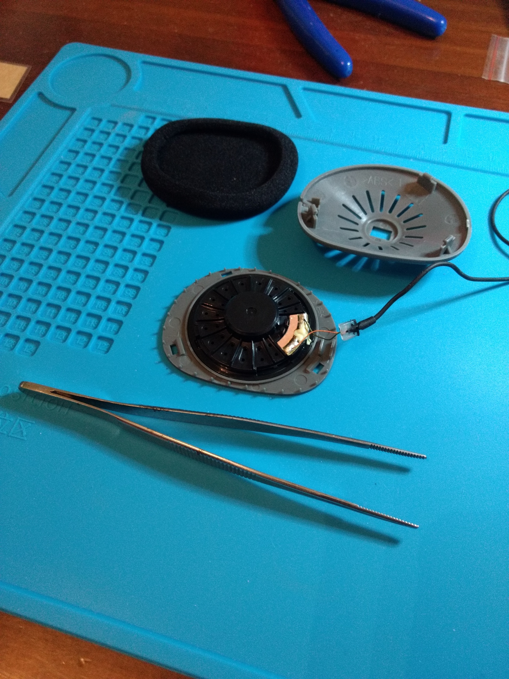
  4. Once the housing are separated, you have the driver side with attached wire. The other side will be a piece of foam, remove that. You will find another pair of tabs that hold the second half of housing. Push them together to pop the housing from the headband.

If all goes well, you should have something that looks like this.

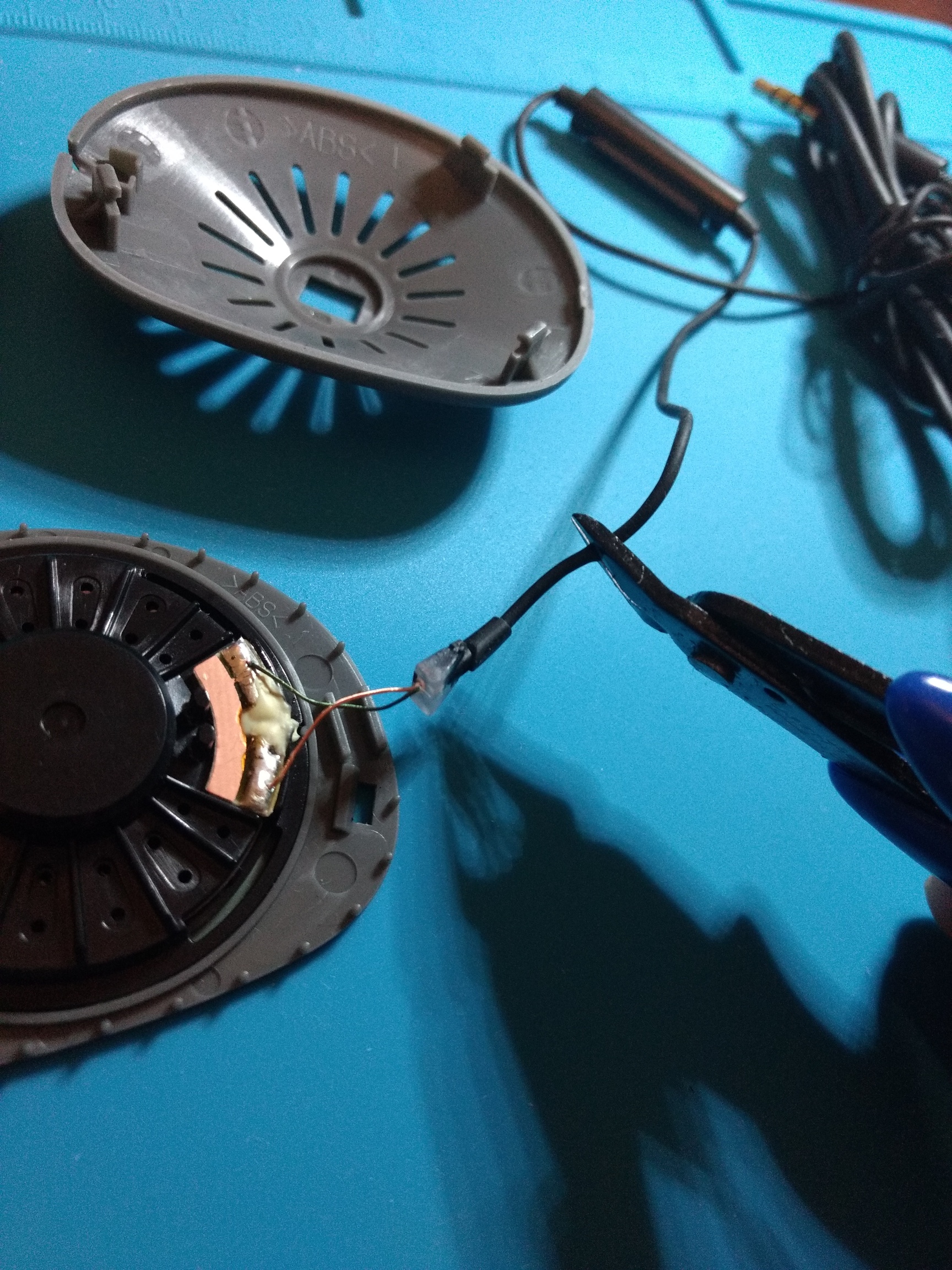
Next, snip the cable. This is the point of no return. In the picture, I cut below the white plastic mold thinking I could pull more wire through the cable like in the PortaPro or KSC75’s. No Koss permanently fixed the wire at the translucent end. Just cut there instead.

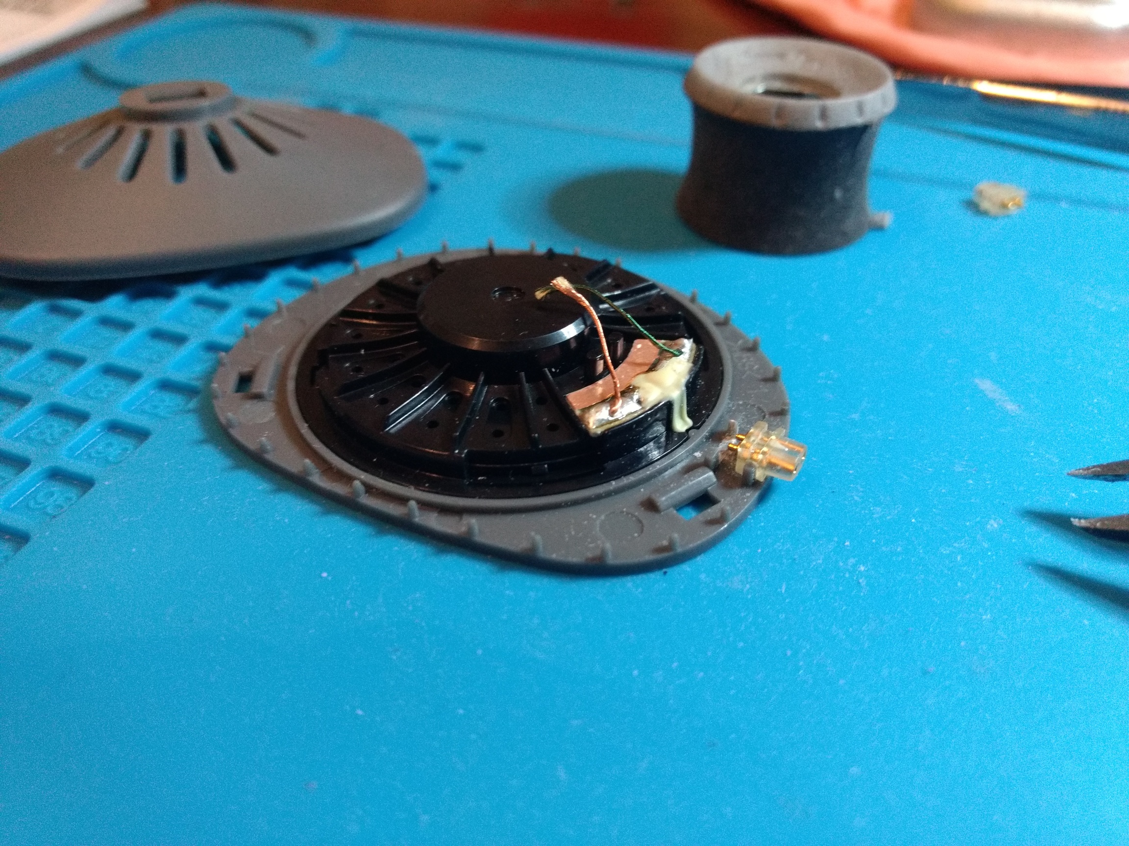
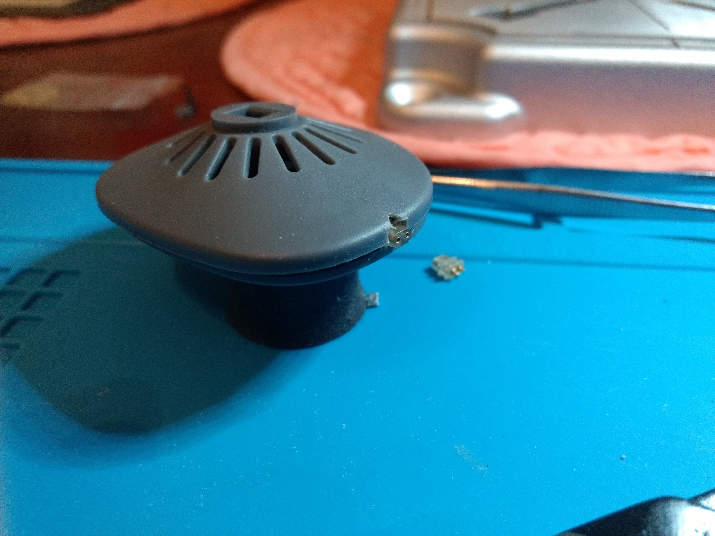
Using a dremel or precision wire cutters (I prefer the wire cutters for this part), enlarge the hole of the housing so it fits the 2-pin connector. Then this is where it differs majorly from my first attempt. There are 2 horizontal plastic bits below the drivers. Instead of cutting them away. You make gap large enough to slide the 2-pin connector grooves right in. You can do this by either sanding it down with a dremel, or using a sharp wire cutter, carefully cut 2 ends, then rock the plastic bit back and forth until it comes off cleanly. The latter method is much more risky because if you aren’t careful, the ends you want to keep could come off anyway.

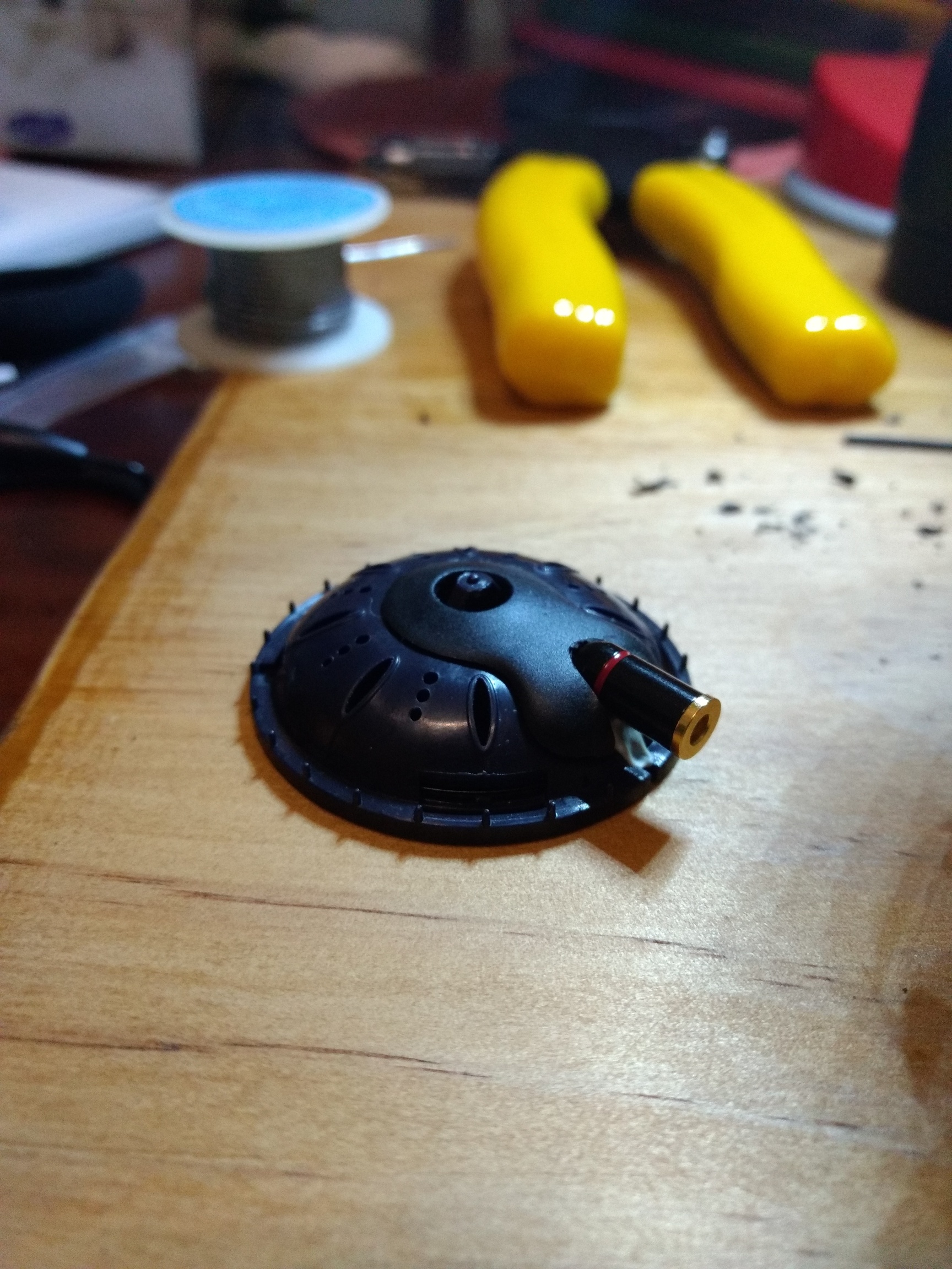
In any case, if you’re successful, the 2 pin connector should slot right into the housing. Allowing a more secure base for you to epoxy like so.

With the enlarged hole for the connectors, it should be a snug and neat fit like so.

Now all that’s left is to solder. I can’t help you with instructions because I am a beginner in soldering myself. However, it should be said that the 2-pin connectors I use have short ends to solder. So a fine tip soldering iron helped a lot here.

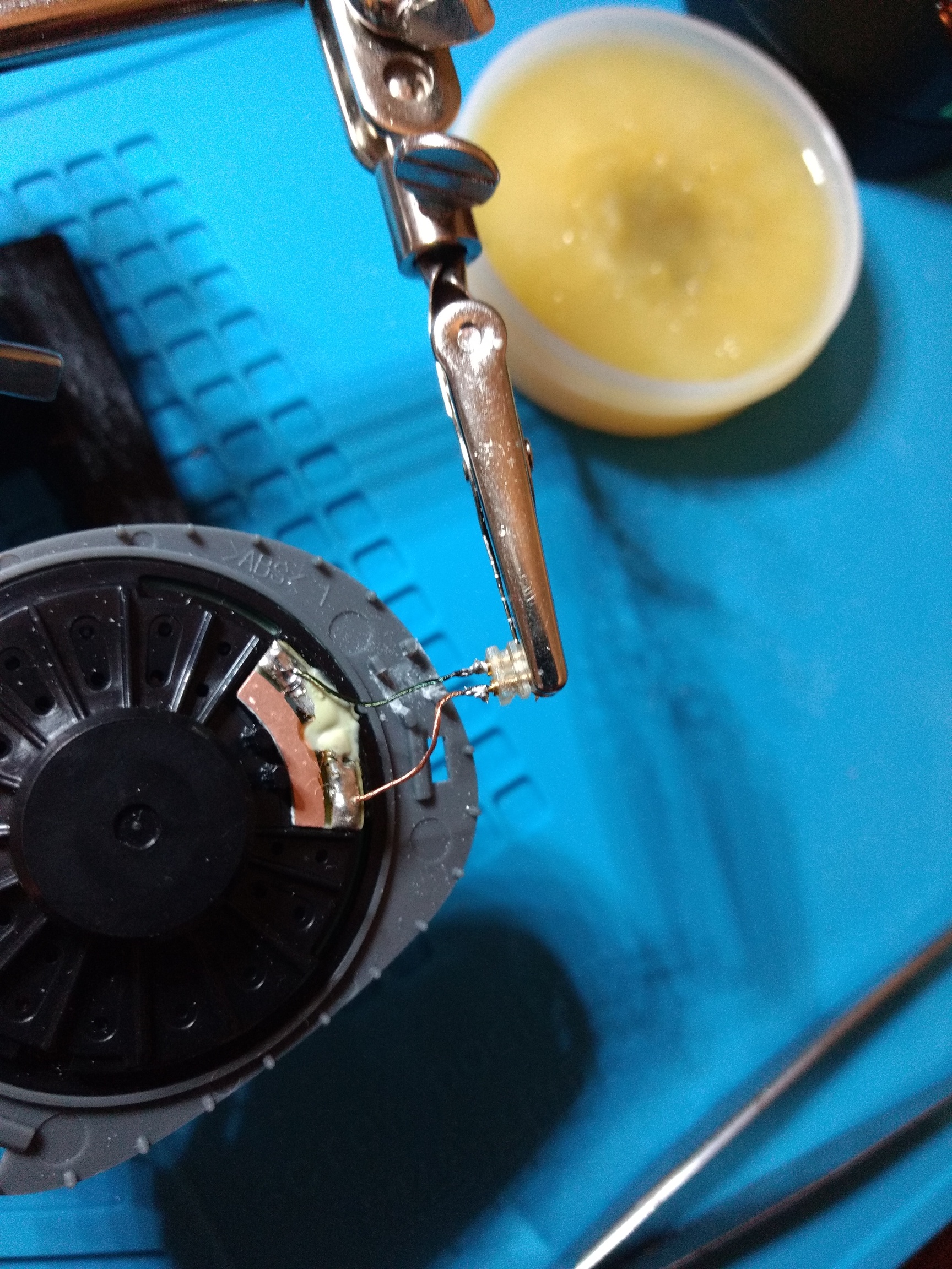
If you have a multimeter, test them after you solder. If not like me, I plugged them into a source (observing polarity: Coloured = hot. Copper = ground) and played left and right channel test.

When that checked out, I epoxy-ed the connectors to the housing. This is another point of no return so you better make sure your soldering holds well.

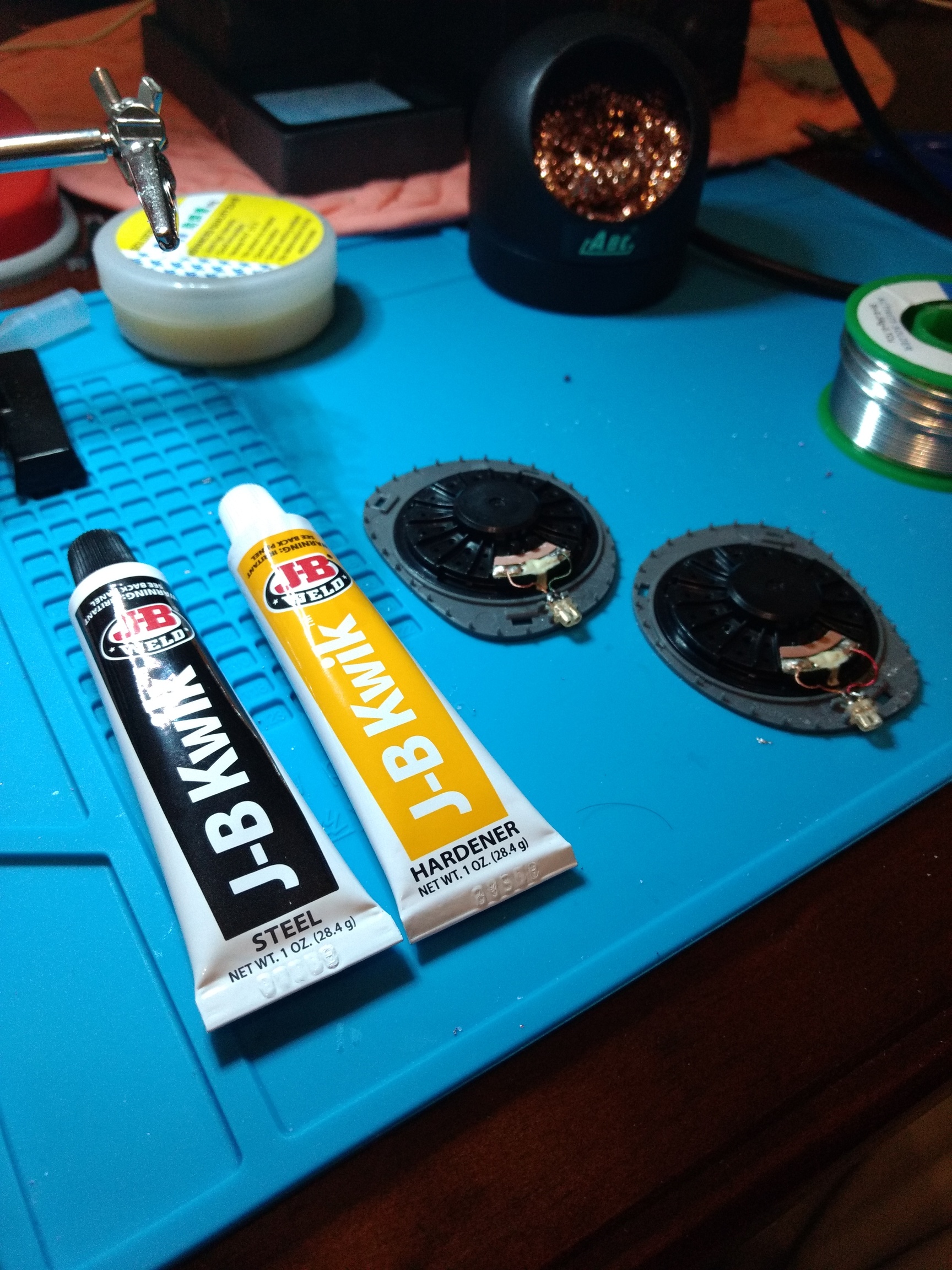
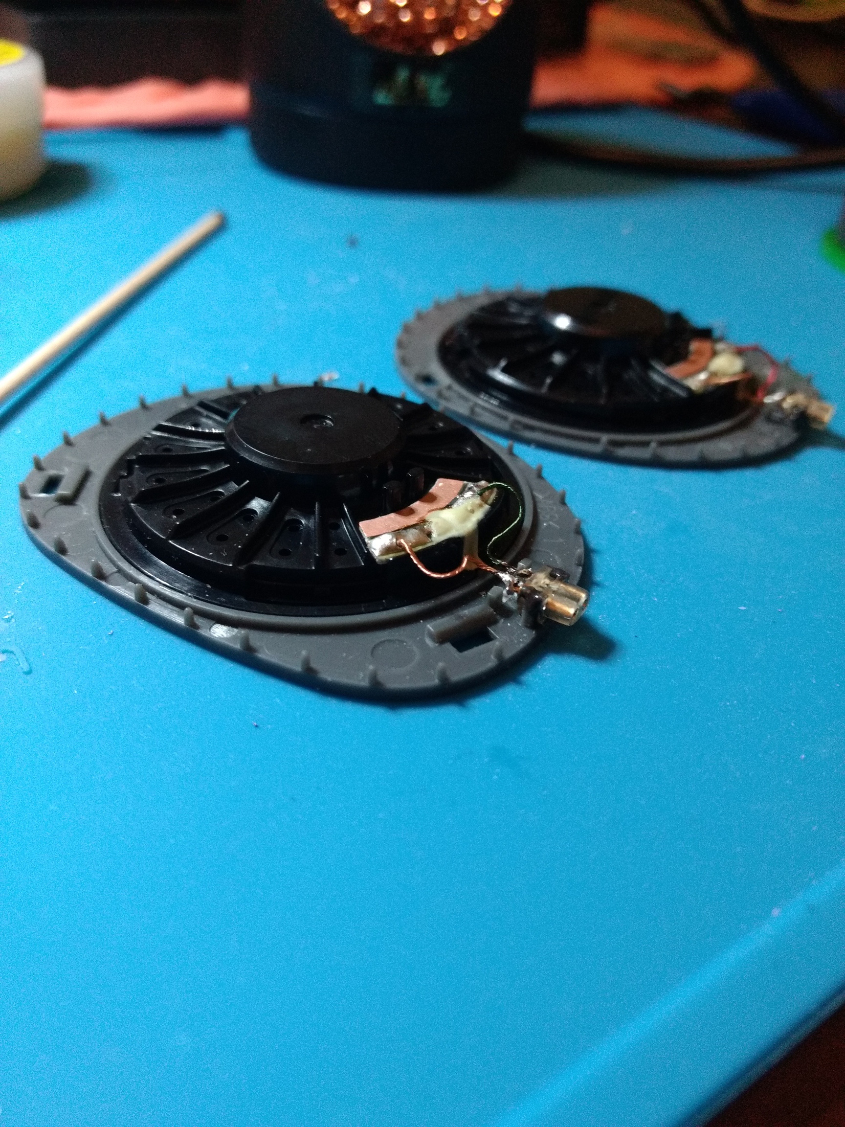
Make sure you leave it to cure for the appropriate amount of time before reassembling it (usually 24 hours). Just leave it the hell alone and resist the urge to marvel at your mad skills. You don’t want to give any excuse for the epoxy to come off after you’ve reassembled the pads.

If you’ve been good, put it all back together, with new pads and you have yourself KPH30i’s that can use any 2-pin cable you want instead of being anchored to the stupid wire it comes with.

So there we have it. I hope that’s comprehensive enough for you to attempt to mod the KPH30i on your own. You do need the right tools for it, but it’s not overly complicated. The goove/slot method should work better to deal with the constant stress of having the wires being attached and detached. Also using 2-pin means less force is needed to remove or attach the cable.

I still think the PortaPros are easier to mod because they are simpler to take apart, but I like both sound signatures, so I don’t mind owning and modding both. The best thing about the detachable cable mod is that you don’t have to use cables. If you’re a crazy person like I am, you can also turn the KPH30i wireless if you have the right gadgets at your disposal.

Cheers and good luck.

41 Likes

Nice tutorial and pictures. Very clearly put together and I know that some people on this forum will greatly appreciate your post and efforts.

7 Likes

Thanks. I certainly hope so. Last I checked, there were much detailed instructions on how to mod KPH30i’s around.

3 Likes

This is awesome. I imagine this could work similarly with the KSC75. I always see MMCX mods but never 2 pin, and I prefer 2 pin connectors too. Many thanks for showing such detailed and in-depth instructions!

4 Likes

I was planning to do the KSC75’s not just as a 2-pin mod, but also to attach the Fiio UTWS1 to it without looking super dorky. I’ve done it as MMXC mod on its own, but yeah, doing it as a 2-pin is much better.

3 Likes

Zeos clued me in that there is a bigger shrouded female connector version of the 0.78mm 2-pin. I found what I think it is on Aliexpress, but it doesn’t have the groove which I’ve detailed in this how-to. Because it’s larger too, it kinda looks good after modding (because it fills the connector hole and then some). I’ll try and get a bunch and pull out some fresh new KPH30i’s for modding.

2 Likes

This is awesome

Nice tutorial, but I do not understand why the two pin connector. If I had one of these, I would prefer to use a MMCX connector instead.

Many people prefer 2 pin due to more durability and it is a more solid connection technically. I prefer it too. But if you like mmcx more personally than that is totally fine. :wink:

1 Like

I believe his original post in the kph30i was with mmcx, he also states his main reason for 2 pin in the post

2 Likes

That was my initial logic (detailed in the post), but given MMCX has such a tight fit, you’re more liable to pull the connector from the casin instead of detaching the cable, especially if you do this repeatedly. 2-pin is a much better solution.

3 Likes

Thanks man. That is something that you could only see by experience. Do you think that with these adapters (they are made for KSC75, but I guess one can use them to the KPH30i also) the MMCX connector coul be a little more secure?

I don’t think it’ll fit. The whole reason I decided on writing this how-to was because it’s a different design than the PortaPro/KSC75. The PortaPro/KSC75 mod method are easier cause there isn’t much to pry open (therefore easier to glue down, whereas the KPH30i is more of a handful.

In fact, my PortaPros and KSC75 mods both use MMCX connectors with no problems, but I can’t with the KPH30i.

Do you think that there is a possible way to do this with the KSC75? I would like to use a 2 pin connector on them rather than an mmcx, if at all possible.

I had problems putting in small connectors to the KSC75 because of the rounded shape. This is how my KSC75 looks like after modding using a larger MMCX connector.

If you can find a 2-pin variant, it should be easy to epoxy down. The method of putting it in is virtually identical to the PortaPro.

2 Likes

Hmm… so perhaps a larger 2 pin? Or sand the openings down to fit a 2 pin connector better?

Larger 2-pin exists (see link on another post I put above). It was just the “square peg in a round hole” issue. Sure you could make it fit, but there were many gaps and less contact area to glue down because of the KSC75’s curved body. My solution was to use a large round body connector. You could probably glue that larger 2-pin to the KSC75 after cutting properly. I’ve yet to try it.

1 Like

Ah okay. Yes, that does make sense.
What soldering iron and other tools would you need to do this? I have never used one before, so I have no idea where to start.

When I started, I got myself:
A generic 30-60W soldering pen type iron
Helping hands (movable little arms with clips to hold whatever you’re soldering)
Rosin core solder (some people will suggest 60/40 solder/lead, but I don’t want cancer)
Brass wool (to clean the iron tip in between soldering)
Rosin paste flux.

After I got confidant, I swapped out the soldering pen to a soldering station which gives a temperature setting instead of wattage.

Other tools I used was a dremel with a grinding/carving bit head set, precision wire cutters and epoxy (I used JB Weld quick drying, non transparent in individual tubes so I can only squeeze out tiny bits of what I want),

Now, I haven’t soldered since high school over a decade ago, so what I did was watch Zeos mod his headphones, and imitated his soldering technique. Obviously there is some trial and error here (also the reason why some initial Koss were destroyed), but I got the hang of it in the end.

3 Likes

Lead causes heavy metal poisoning before the cancer gets you :stuck_out_tongue_winking_eye:

I like my leaded solder (Sn60/Pb38/Cu2) more than my fancy stuff (Sn96.5/Ag3/Cu0.5). The lead just makes it flow and stay flexible so much better.

3 Likes